Gear and electric power steering device

a technology of electric power steering and gear, which is applied in the direction of gearing, hoisting equipment, transportation and packaging, etc., can solve the problems of insufficient space between metal core and synthetic resin tooth body, insufficient rotation prevention groove, and complicated relative rotation, so as to increase the coupling strength and increase the durability of the gear, and thus the durability of the electric power steering device.

Inactive Publication Date: 2008-07-31
JTEKT CORP
View PDF4 Cites 23 Cited by
  • Summary
  • Abstract
  • Description
  • Claims
  • Application Information

AI Technical Summary

Benefits of technology

[0010]The invention provides a gear and an electric power steering device, in which the area where a metal core and a synthetic resin tooth body are coupled to each other is made sufficiently large without increasing the length of the gear in a tooth-width direction, and the coupling strength between the metal core and the synthetic resin tooth body in a rotational direction is increased, using a simple structure for preventing the relative rotation of the metal core and the synthetic resin tooth body.
[0012]According to the first aspect, the rotation prevention grooves are formed in the two portions, that is, the outer peripheral portion and the inner peripheral portion of the cylindrical portion. Therefore, the rotation prevention grooves are made sufficiently long without increasing the length of the gear in the tooth-width direction. Thus, it is possible to increase the coupling strength between the metal core and the synthetic resin tooth body in the rotational direction. Further, the rotation prevention grooves are formed on the outer peripheral portion and the inner peripheral portion by cold forging or press forming. Therefore, the structure of the metal core is simple, though the rotation prevention grooves are formed on the outer peripheral portion and the inner peripheral portion of the metal core. This reduces cost.
[0014]With the configuration, the guard portion, which extends outwardly in the radial direction from the other end, is provided in the cylindrical portion. Therefore, when the rotation prevention grooves are formed on the outer peripheral portion by cold forging, the guard portion prevents formation of burrs at the edges of the rotation prevention grooves. This eliminates the process for removing burrs, and prevents occurrence of a crack in the synthetic resin tooth body.
[0016]With this configuration, the rotation prevention grooves formed on the outer peripheral portion and the rotation prevention grooves formed on the inner peripheral portion extend in the tooth-width direction. Therefore, it is possible to sufficiently increase the coupling strength in the rotational direction at both sides of the gear in the tooth-width direction (the one end side and the other end side), though the guard portion is provided. Thus, it is possible to further increase durability even when the gear is used at a location to which relatively high rotational torque is applied.
[0018]According to the second aspect, it is possible to sufficiently increase the coupling strength between the metal core and the synthetic resin tooth body in the rotational direction without increasing the length of the gear in the tooth-width direction. Thus, it is possible to increase the durability of the gear, and therefore, the durability of the electric power steering device even when relatively high rotational torque is applied to the gear, for example, by turning a steering wheel while a vehicle is stopped.

Problems solved by technology

However, in the gear that includes the metal core formed by cutting process or cold forging, because the relative rotation of the synthetic resin tooth body and the metal core is prevented only by the rotation prevention grooves formed on the outer peripheral portion of the metal core, the rotation prevention grooves are not sufficiently long, that is, the area where the metal core and the synthetic resin tooth body are coupled to each other is not sufficiently large.
However, the structure for preventing the relative rotation is complicated, and therefore, the structure of a die used to form the metal core is also complicated.

Method used


Image

  • Gear and electric power steering device
  • Gear and electric power steering device
  • Gear and electric power steering device

Examples


Embodiment Construction

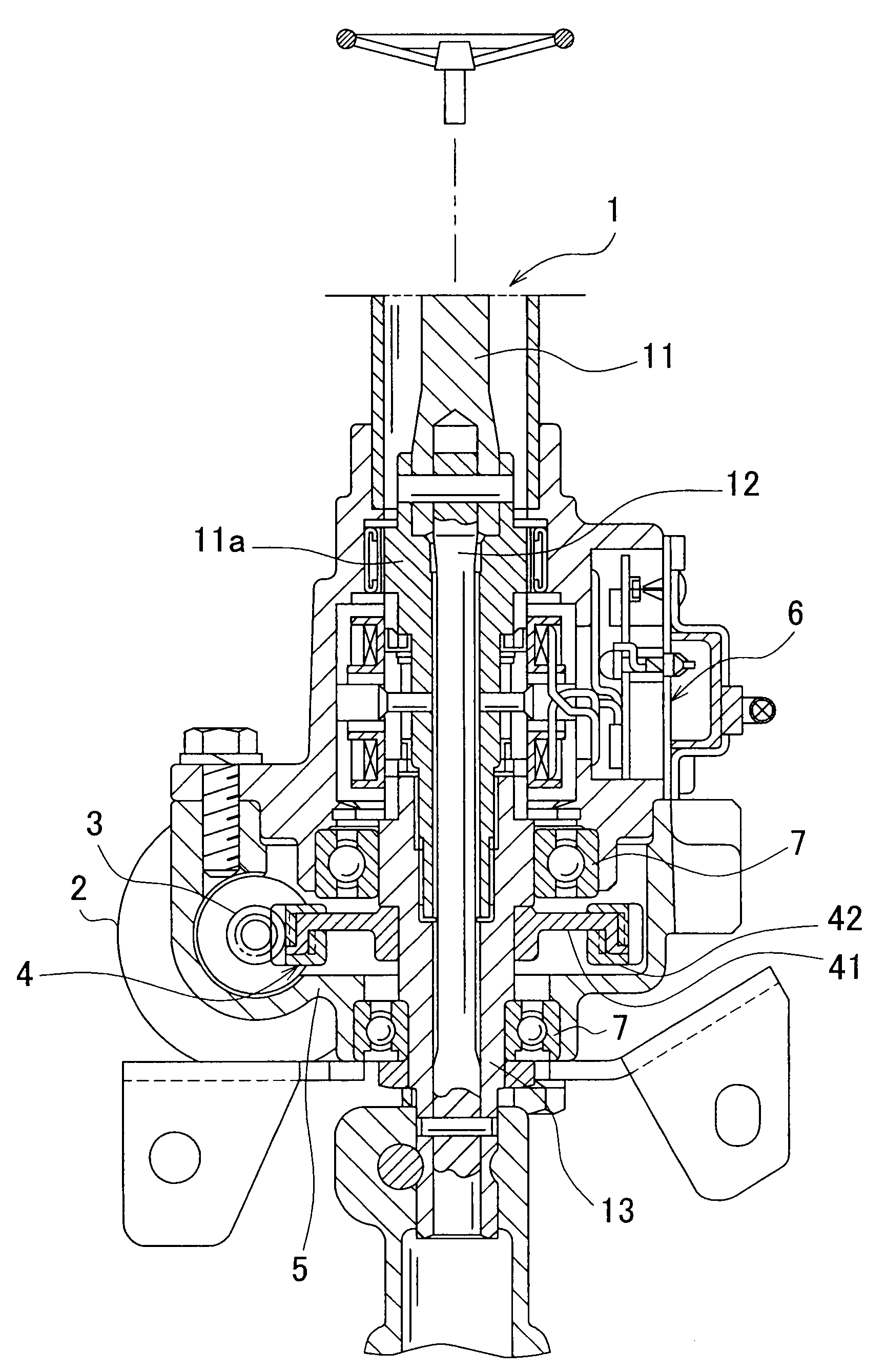
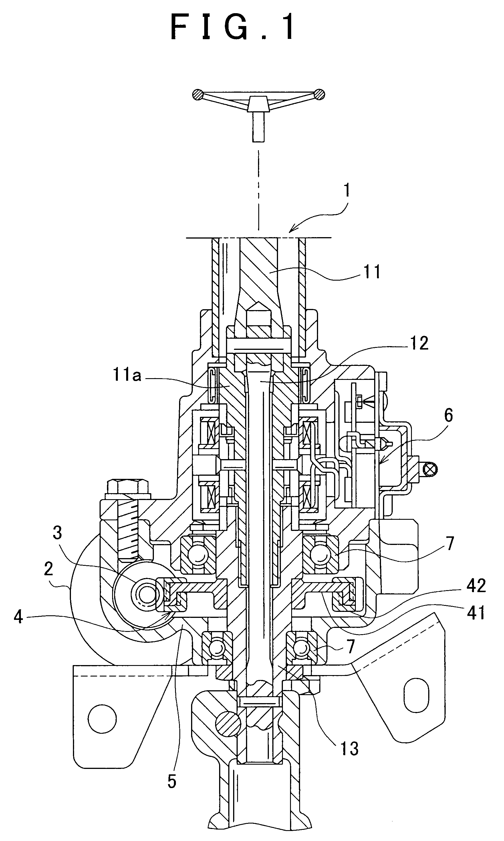
[0024]Hereinafter, an embodiment of the invention will be described in detail with reference to the drawings. FIG. 1 is a cross sectional view showing the configuration of an electric power steering device according to the embodiment of the invention. The electric power steering device includes a steering shaft 1, an electric motor 2 for steering assistance, a small gear 3, a large gear 4, a housing 5, and a torque sensor 6. The steering shaft 1, which functions as steering means, is connected to a steering wheel that functions as an operating member. The large gear 4 engages with the small gear 3. The small gear 3 and the large gear 4 increase the rotating force of the electric motor 2, and apply the increased rotating force to the steering shaft 1. The housing 5, which functions as a support member, supports the small gear 3 and the large gear 4 in a manner such that the small gear 3 and the large gear 4 can rotate. The torque sensor 6 detects torque that is applied to the steerin...


PUM


Abstract

A gear includes a metal core and a synthetic resin tooth body. The metal core includes a cylindrical portion, and a disc portion that extends inwardly in a radial direction from one end of the cylindrical portion. The synthetic resin tooth body is coupled to the cylindrical portion of the metal core. A plurality of rotation prevention grooves is formed on the outer peripheral portion of the cylindrical portion, and a plurality of rotation prevention grooves is formed on the inner peripheral portion of the cylindrical portion.

Description

INCORPORATION BY REFERENCE[0001]The disclosure of Japanese Patent Application No. 2007-16937 filed on Jan. 26, 2007 including the specification, drawings and abstract is incorporated herein by reference in its entirety.BACKGROUND OF THE INVENTION[0002]1. Field of the Invention[0003]The invention relates to a gear that is formed by coupling a synthetic resin tooth body to the outer peripheral portion of a metal core, and an electric power steering device that includes the gear.[0004]2. Description of the Related Art[0005]Japanese Patent Application Publication No. 2001-206230 (JP-A-2001-206230) describes an electric power steering device for a vehicle, in which steering torque applied to an input shaft connected to a steering wheel is detected based on the relative rotation of the input shaft and an output shaft that is coaxially connected to the input shaft via a torsion bar, and an electric motor for steering assistance is driven based on, for example, the detected torque. The rota...

Claims


Application Information

Patent Timeline
Patent Type & Authority Applications(United States)
IPC IPC(8): F16H35/00
CPCB62D5/0409F16H55/06Y10T74/19921Y10S74/10Y10T74/19828F16H2055/065
Inventor IMAGAKI, SUSUMUYAMADA, WATARUKIKUCHI, ARATA
Owner JTEKT CORP
Why Eureka
Try Eureka