Plasma reactor for the treatment of large size substrates

a plasma reactor and large-scale technology, applied in the direction of plasma technique, chemical vapor deposition coating, coating, etc., can solve the problems of non-uniformity, other non-uniformities in the reactor, and the intensity of plasma along the reactor cannot be uniform

Inactive Publication Date: 2008-08-07
EVATEC
View PDF5 Cites 2 Cited by
  • Summary
  • Abstract
  • Description
  • Claims
  • Application Information

AI Technical Summary

Problems solved by technology

An important problem was noted especially if the RF frequency is higher than 13.56 MHz and a large size (surface) substrate is used, in such a way that the reactor size is no more negligible relative to the free space wavelength of the RF electromagnetic wave.
Then, the plasma intensity along the reactor can no longer be uniform.
Other non uniformities can also occur in a reactor, for example non uniformities induced by the reactive gas provided for the plasma process.

Method used


Image

  • Plasma reactor for the treatment of large size substrates
  • Plasma reactor for the treatment of large size substrates
  • Plasma reactor for the treatment of large size substrates

Examples


Embodiment Construction

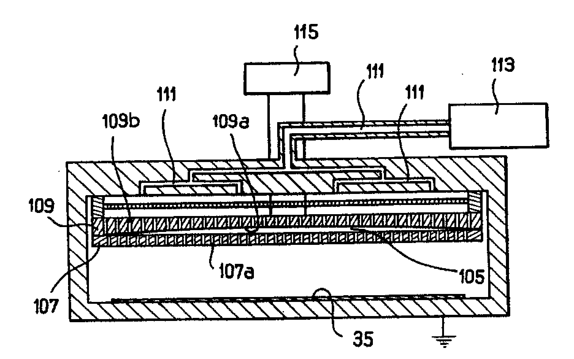
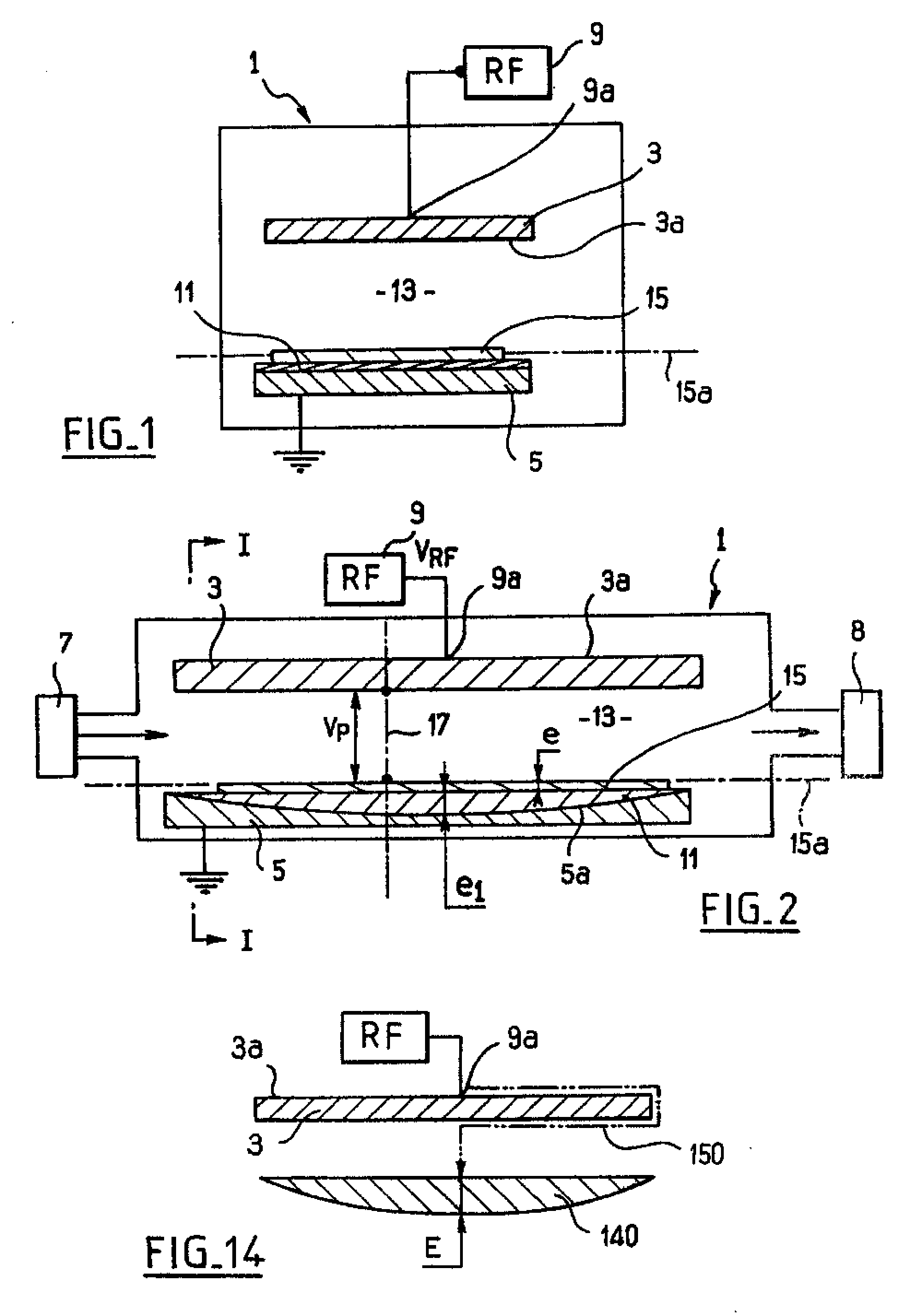
[0050]In FIGS. 1 and 2, the reactor is referenced 1. Reactor 1 encloses two metallic electrodes 3, 5 which have an outer surface, 3a, 5a, respectively. The electrodes are spaced from each other.

[0051]A gas source 7 provides the reactor with a reactive gas (or a gas mixture) in which the plasma is generated through a radiofrequency discharge (see the above table). Pumping means 8 are further pumping the gas, at another end of the reactor.

[0052]The radiofrequency discharge is generated by a radiofrequency source 9 connected at a location 9a to the upper electrode 3. The location 9a is centrally arranged on the back of the external surface 3a of the electrode.

[0053]These schematic illustrations further show an extra-capacitor 11 electrically in series with the plasma 13 and a substrate 15 located thereon.

[0054]The plasma 13 can be observed in the internal space (having the same numeral reference) which extends between the electrode 3 and the substrate 15.

[0055]The substrate 15 can be a...


PUM

PropertyMeasurementUnit
frequenciesaaaaaaaaaa
frequencyaaaaaaaaaa
RF frequencyaaaaaaaaaa

Abstract

A radiofrequency plasma reactor with first and second spaced electrodes has a concave surface facing a substrate supporting surface. A process area between the electrodes has a gas inlet for a process gas. A radiofrequency generator for frequencies greater than 13.56 MHz is connected to an electrode for generating a plasma discharge in and a gas outlet evacuates process gas. A dielectric layer has a convex surface engaging the concave electrode surface and an opposite planar surface. The substrate supporting surface receives a substrate of at least 0.7 m and defines a boundary of the process area to be exposed to the plasma. The dielectric layer is electrically in series with the substrate and plasma discharge and has capacitance per unit surface values which are not uniform for a distribution profile to compensate process non-uniformity along the working surface.

Description

CROSS REFERENCE TO RELATED APPLICATIONS[0001]This is a divisional of application Ser. No. 09 / 824,936 filed Apr. 3, 2001, which is a divisional of application Ser. No. 09 / 401,158 filed Sep. 22, 1999, now U.S. Pat. No. 6,228,438, and which claims priority of Swiss application number 1466 / 99 filed Aug. 10, 1999. The disclosures of all of these applications are incorporated here by reference in their entireties.FIELD AND BACKGROUND OF THE INVENTION[0002]The invention relates to a capacitively coupled radiofrequency (RF) plasma reactor and to a process for treating at least one substrate in such a reactor. Especially, the present invention applies to a large size capacitive capacitively coupled (RF) plasma reactor.[0003]Often, such a reactor is known as a “capacitive” RF glow discharge reactor, or planar plasma capacitor or parallel plate RF plasma reactor, or as a combination of the above named.[0004]Capacitive RF plasma reactors are typically used for exposing a substrate to the proces...

Claims


Application Information

Patent Timeline
Patent Type & Authority Applications(United States)
IPC IPC(8): C23C16/509H05H1/46H01J37/32H01L21/205H01L21/302H01L21/3065
CPCC23C16/4583C23C16/509H01J37/32091H01J37/32192H01J37/32559H01J37/32348H01J37/32532H01J37/32541H01J37/32238H05H1/30
Inventor SCHMITT, JACQUES
Owner EVATEC
Why Eureka
Try Eureka