Hydrogen dispensing station and method of operating the same

a technology of hydrogen dispensing station and hydrogen dispensing station, which is applied in the direction of liquid handling, container discharging method, packaging goods type, etc., can solve the problems of less than complete filling, limited dispensing rate of hydrogen by serial approach, and inability to meet the requirements of dispensing,

Inactive Publication Date: 2008-08-07
AIR PROD & CHEM INC
View PDF18 Cites 39 Cited by
  • Summary
  • Abstract
  • Description
  • Claims
  • Application Information

AI Technical Summary

Benefits of technology

[0015]Additionally or alternatively, the hydrogen dispensing station may further comprise a first conduit containing hydrogen having a first temperature; a second conduit containing hydrogen having a second temperature different from the first temperature; and the means for limiting receiving vessel gas temperature during dispensing may be a valve array or multi-way valve in fluid communication with the first conduit and the second conduit, the valve array or multi-way valve for selectively passing hydrogen from the first conduit and hydrogen from the second conduit simultaneously to the at least two hydrogen service ports responsive to the temperature control command. Alternatively, the valve array or multi-way valve may be used for selectively blending hydrogen from the first conduit and hydrogen from the second conduit responsive to the temperature control command. The second temperature may be at least 30 Celsius degrees less than the first temperature.
[0016]A method of operating a hydrogen dispensing station is disclosed. The method of operating the hydrogen dispensing station comprises generating a control command in a controller responsive to a fast dispensing rate algorithm; electronically communicating the control command to a means for limiting receiving vessel gas temperature during dispensing; passing a hydrogen-containing feed stream having a first temperature to a means for limiting receiving vessel gas temperature during dispensing to form a regulated stream; simultaneously passing a first portion of the regulated stream to a first hydrogen service port and a second portion of the regulated stream to a second hydrogen service port; and simultaneously dispensing a first dispensing stream from the first hydrogen service port into a first receiving vessel, the first dispensing stream obtained from the first portion of the regulated stream, and dispensing a second dispensing stream from the second hydrogen service port into a second receiving vessel, the second dispensing stream obtained from the second portion of the regulated stream.
[0017]The control command may be a pressure ramp rate control command, the means for limiting receiving vessel gas temperature during dispensing may be a programmable pressure control valve, and the regulated stream may be a pressure ramp rate regulated stream. The method may further comprise operating the programmable pressure control valve responsive to the pressure ramp rate control command thereby forming the pressure ramp rate regulated stream.
[0018]The control command may be a temperature control command, the means for limiting receiving vessel gas temperature during dispensing may be a valve array, and the regulated stream may be a temperature regulated stream. The method may further comprise passing a second hydrogen-containing feed stream having a second temperature different from the first temperature to the valve array; and regulating the hydrogen-containing feed stream and the second hydrogen-containing feed stream via the valve array responsive to the temperature control command thereby forming the temperature regulated stream. The second temperature may be at least 30 Celsius degrees less than the first temperature.
[0019]The control command may be a temperature control command, the means for limiting receiving vessel gas temperature during dispensing may be a coolant flow regulated heat exchanger, and the regulated stream may be a temperature regulated stream. The method may then further comprise regulating a coolant flow through the coolant flow regulated heat exchanger responsive to the temperature control command thereby forming the temperature regulated stream.
[0020]The control command may be a temperature control command, the means for limiting receiving vessel gas temperature during dispensing may be a valve array, and the regulated stream may be a temperature regulated stream. The method may then further comprise selectively passing the hydrogen-containing feed stream to a heat exchanger via the valve array responsive to the temperature control command thereby forming the temperature regulated stream.

Problems solved by technology

After the tank is filled, the temperature and pressure inside the tank will decrease as the gas cools, which may result in a less than complete fill.
Hydrogen dispensing by a serial approach is subject to delays and interruptions if issues arise with either the dispensing station or a receiving vessel.
The maximum rate for dispensing to a receiving vessel, while at the same time maximizing the amount of hydrogen dispensed, is limited due to potential temperature rise of the receiving vessel gas temperature during dispensing.
Dispensing to multiple receiving vessels where the receiving vessels are constructed of different materials and are different sizes may pose additional challenges.

Method used


Image

  • Hydrogen dispensing station and method of operating the same
  • Hydrogen dispensing station and method of operating the same
  • Hydrogen dispensing station and method of operating the same

Examples


example 1

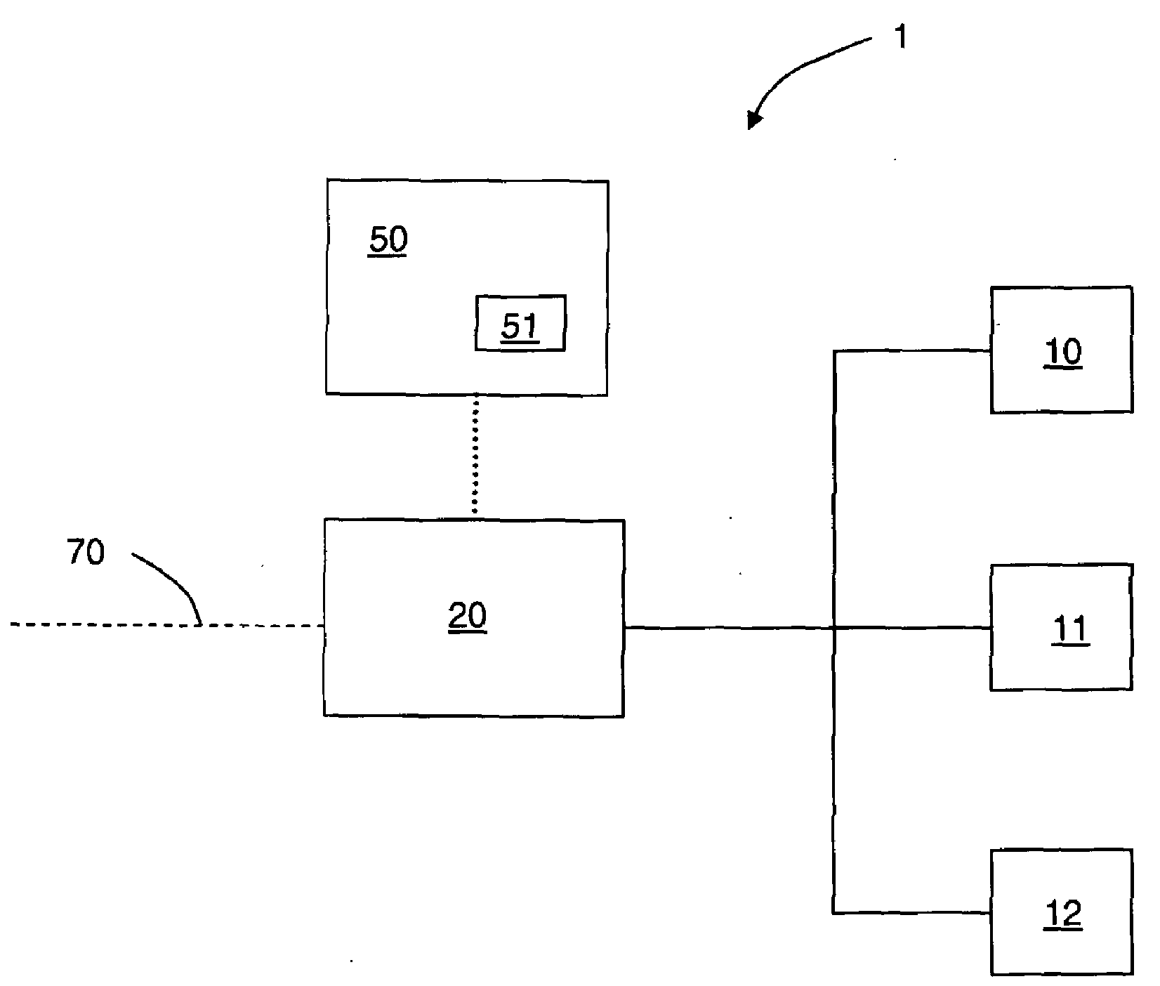
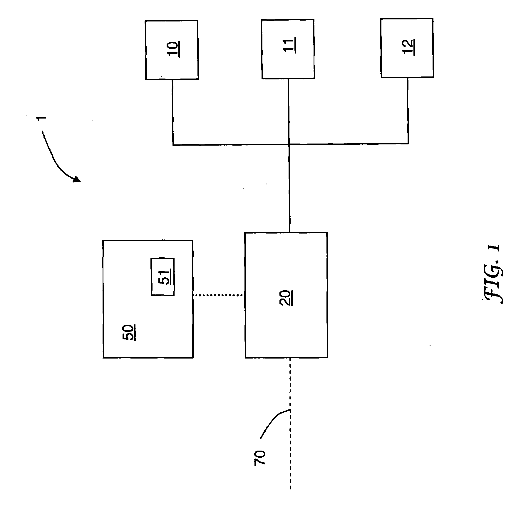
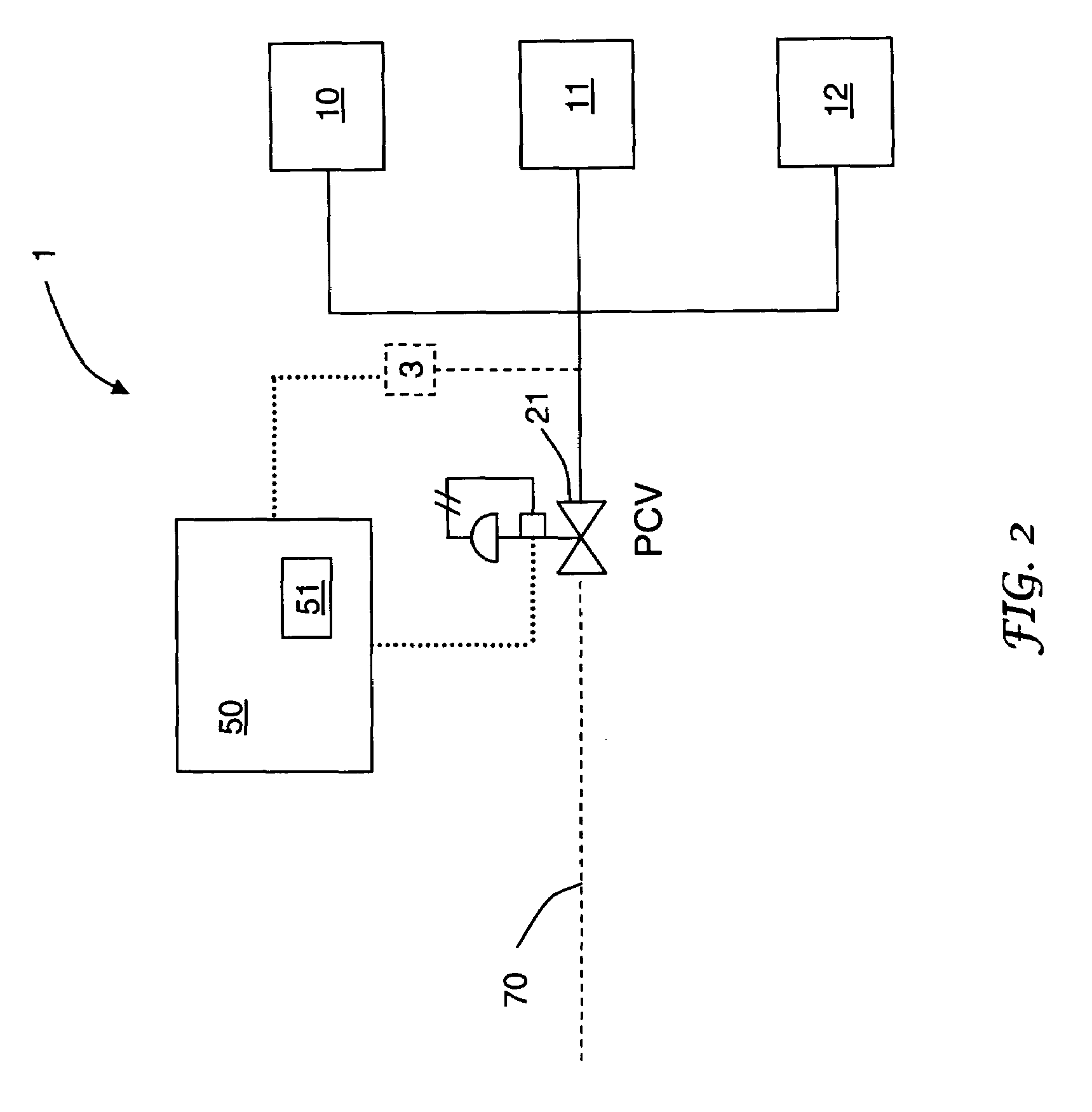
[0090]Referring to FIG. 2, a first receiving vessel containing hydrogen having a pressure of about 50 bar and a target pressure of about 750 bar is connected to hydrogen service port 10. Controller 50 sends a signal to programmable pressure control valve 21. Flow is initiated at time zero and the pressure ramp rate, controlled by the programmable pressure control valve 21, is about 25 bar / min according to the signal. A second receiving vessel containing hydrogen having a pressure of about 100 bar and a target pressure of about 750 bar is connected to hydrogen service port 11 within 1 minute of time zero. At time equals two minutes, both receiving vessels will have pressure of about 100 bar. At this time, flow is initiated to the second receiving vessel and flow is continued to the first receiving vessel. Hydrogen is dispensed simultaneously to the first receiving vessel and the second receiving vessel at a pressure ramp rate of 25 bar / min via programmable pressure control valve 21. ...

example 2

[0094]Referring to FIG. 5, a first receiving vessel containing hydrogen having a pressure of about 25 bar and a target pressure of about 500 bar is connected to hydrogen service port 10. Flow is initiated by controller 50 at time zero. Flow is passed from conduit 70 to the valve array 23 and through valve 32, thereby bypassing the heat exchanger 40. A second receiving vessel containing hydrogen having a pressure of about 100 bar and a target pressure of about 750 bar is connected to hydrogen service port 11 within 1 minute of time zero. The pressure in the first receiving vessel is less than the pressure in the second receiving vessel. When the pressure in the first receiving vessel and the pressure in the second receiving vessel are the same, flow is initiated to the second receiving vessel and flow is continued to the first receiving vessel.

[0095]At time equals 3 minutes, valve 32 closes and valve 31 opens thereby passing hydrogen from conduit 70 through the heat exchanger 40 and ...


PUM

PropertyMeasurementUnit
temperatureaaaaaaaaaa
pressureaaaaaaaaaa

Abstract

A hydrogen dispensing station and method of operating a hydrogen dispensing station for dispensing to multiple receiving vessels. The station and method limit receiving vessel gas temperature during dispensing. Various components used to limit receiving vessel gas temperature during dispensing are mutual to multiple hydrogen service ports. Receiving vessel gas temperature during dispensing may be affected by pressure ramp rate control, cooling of hydrogen in a heat exchanger, and/or use of a lower temperature hydrogen source stream.

Description

BACKGROUND[0001]The present invention is related to a hydrogen dispensing station and a method of operating a hydrogen dispensing station. More particularly, the present invention is directed to a hydrogen dispensing station and method useful for simultaneously dispensing hydrogen gas into at least two receiving vessels.[0002]Because of the interrelationship between the temperature, pressure, and density of gases, the amount of hydrogen, H2, that can safely be introduced into a receiving vessel, such as a vehicle storage tank, during refueling necessarily depends upon factors such as the volume, design pressure, and temperature of the receiving vessel, and the temperature and pressure of the compressed gas inside the tank. Industry convention sets the pressure rating for H2 fuel tanks at the standard temperature of 15 degrees Celsius, so nominal pressure ratings such as 250 bar (25 MPa), 350 bar (35 MPa), 500 bar (50 MPa) and 700 bar (70 MPa), correspond to an internal gas temperatu...

Claims


Application Information

Patent Timeline
Patent Type & Authority Applications(United States)
IPC IPC(8): B65B31/00
CPCF17C5/007Y02E60/321F17C13/025F17C13/026F17C2221/012F17C2223/0123F17C2223/036F17C2225/0123F17C2225/036F17C2227/0337F17C2227/039F17C2227/043F17C2250/032F17C2250/043F17C2250/0439F17C2250/0626F17C2250/0631F17C2260/023F17C2270/0139F17C2270/0168F17C2270/0171F17C2270/0176F17C2270/0178F17C5/06Y02P90/45Y02E60/32
Inventor COHEN, JOSEPH PERRYCOPEMAN, TAMA MAYA
Owner AIR PROD & CHEM INC
Why Eureka
Try Eureka