Particle-optical apparatus for simultaneous observing a sample with particles and photons

Active Publication Date: 2008-08-07
FEI CO
View PDF12 Cites 46 Cited by
  • Summary
  • Abstract
  • Description
  • Claims
  • Application Information

AI Technical Summary

Benefits of technology

[0026]The invention relates to a particle-optical apparatus, such as an ESEM®, for simultaneous observing a sample with particles and photons. A pressure limiting aperture (PLA) is placed in a diaphragm between the objective lens of the ESEM® and the sample position. The distance between the sample position and the aperture is sufficiently small to allow a large collection angle of the photons through this aperture. A mirror is placed between th

Problems solved by technology

A problem occurring at such low pressures is that the sample dehydrates, leading to artefacts.
A known limitation of such instruments is that many particles are scattered out of the primary beam of particles into the so-named skirt region.
As described in Newbury (page 572, left column), a related problem is the lowering of the signal-to-noise ratio S/N of the signal obtained with e.g. the secondary particle detector.
However, as less and less particles are available in the unscattered part of th

Method used


Image

  • Particle-optical apparatus for simultaneous observing a sample with particles and photons
  • Particle-optical apparatus for simultaneous observing a sample with particles and photons
  • Particle-optical apparatus for simultaneous observing a sample with particles and photons

Examples


Embodiment Construction

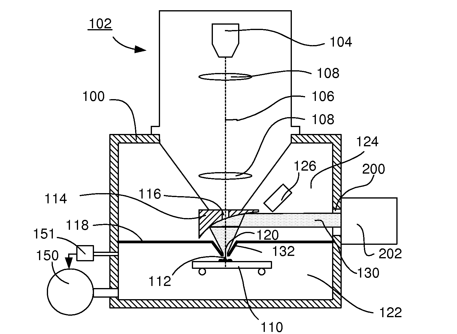
[0033]To that end the apparatus according to the invention is characterized in that a diaphragm is placed between the sample position and the mirror, said diaphragm dividing a first volume in which the sample position is located from a second volume, said diaphragm showing an aperture round the particle-optical axis for passing particles produced by the particle-optical column and for passing light between the mirror and the sample position, the aperture limiting the gas flow from the first volume to the second volume to such a value, that, when the pressure at the sample position is the equilibrium pressure of a fluid with an equilibrium pressure above 1 mbar, the evacuation means can evacuate the second vacuum to a pressure sufficiently low to cause negligible scattering of the particle beam in the second volume when compared to the scattering in the first volume, and the distance between the aperture and the sample position can be adjusted to be, or is fixed at, less than four ti...


PUM


Abstract

A particle-optical apparatus, such as an ESEM®, for simultaneous observing a sample with particles and photons. A pressure limiting aperture (PLA) is placed in a diaphragm between the objective lens of the ESEM® and the sample position. The distance between the sample position and the aperture is sufficiently small to allow a large collection angle of the photons through this aperture. A mirror is placed between the diaphragm and the objective lens. Due to the large collection angle for photons a large NA is achieved. The small distance between sample position and aperture also result in less scattering of electrons than occurs in ESEM's where a mirror is placed between aperture and sample position, as the electrons have to travel through only a limited length in a high pressure area. Embodiments describe combinations where e.g. an immersion lens is used.

Description

[0001]This Application claims priority from U.S. Provisional Application No. 60 / 009,005, filed Feb. 6, 2008, which is hereby incorporated by reference.BACKGROUND OF THE INVENTION [0002]The invention relates to a particle-optical apparatus comprising: a vacuum chamber, an particle-optical column mounted on the vacuum chamber for producing a particle beam round a particle-optical axis, said particle-optical column comprising a particle source, a sample carrier located in the vacuum chamber for carrying a sample at a sample position, said sample position located on the particle-optical axis, a mirror collecting light emitted from the sample position or focussing light on the sample position, said mirror showing a through-hole round the particle-optical axis, and evacuation means for evacuating the apparatus.[0003]The invention also relates to a kit for upgrading an existing apparatus, and to a method for using such an apparatus.[0004]Such an apparatus is known from U.S. Pat. No. 6,885,...

Claims


Application Information

Patent Timeline
IPC IPC(8): H05H3/02
CPCH01J37/228H01J37/244H01J37/256H01J2237/2808H01J2237/188H01J2237/2608H01J37/28
Inventor KNOWLES, WILLIAM RALPH
Owner FEI CO
Why Eureka
Try Eureka