Light source device and projector

Inactive Publication Date: 2008-08-07
SEIKO EPSON CORP
View PDF2 Cites 2 Cited by
  • Summary
  • Abstract
  • Description
  • Claims
  • Application Information

AI Technical Summary

Benefits of technology

[0010]An advantage of the invention is to provide a light source device capable of improving the light efficiency while preventing leakage of a microwave from a light emitting section, and a projector provided with the light source device.
[0011]A light source device according to an aspect of the invention includes a microwave generating section for generating a microwave, a reflector connected to the microwave generating section, and a microwave electrodeless lamp disposed inside a cavity, the cavity including the reflector and a metallic chamber covering an opening section of the reflector, the chamber including a tube member having an opening section for communicating the inside and the outside of the cavity to lead a light flux out of the chamber, and a bore diameter D of the opening section, a length L of the tube member, a wavelength λ of the microwave, and a wavelength Λ of the light flux satisfying Λ<D≦(¼)λ, L≧(¼)λ, and D+T=(½) .
[0012]Further, it is preferable that the bore diameter D of the opening section is equal to (¼)λ, and the length L of the tube member is equal to (¼)λ.
[0013]According to this aspect of the invention, the tube member c

Problems solved by technology

According to the Document 1 described above, since there is a light flux reflected by the meshed metal section, a problem of deterioration of the light efficiency arises.
Further, it is projected that the meshed metal is heated by the heat radiation from the electrodeless discharge lamp, thus the structural strength of the meshed metal is weakened.
By increa

Method used


Image

  • Light source device and projector
  • Light source device and projector
  • Light source device and projector

Examples


first embodiment

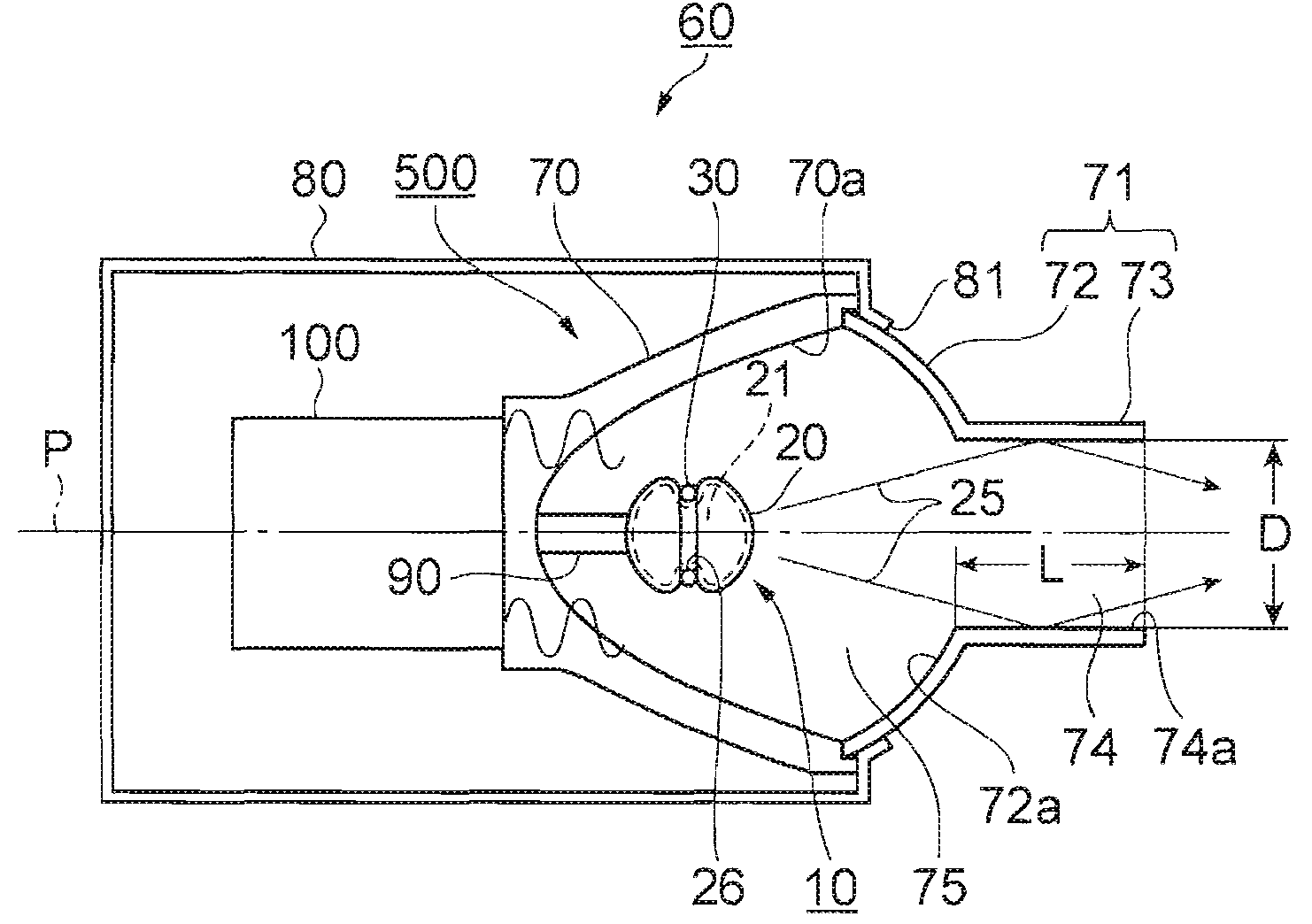
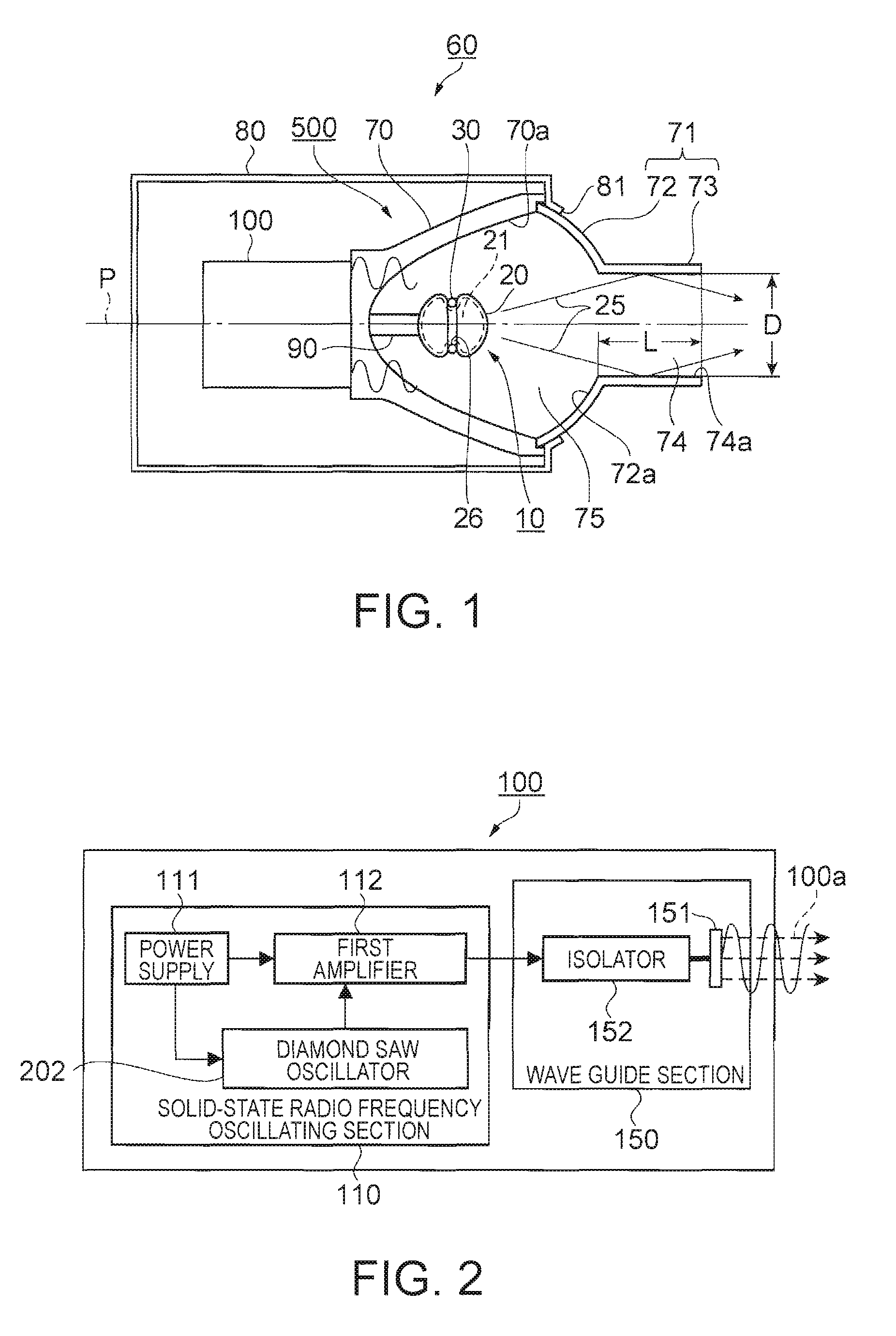
[0038]FIG. 1 is a cross-sectional view showing a schematic structure of a light source device according to a first embodiment of the invention. In FIG. 1, a light source device 60 is configured including a microwave generating section 100, a light emitting section 500, and a light source housing 80 as a microwave blocking section for housing the microwave generating section 100 and the light emitting section 500. Further, the light emitting section 500 is configured having a microwave electrodeless lamp 10 (hereinafter also referred to simply as a lamp), a reflector 70, a metallic chamber 71 covering an opening section of the reflector 70, and a support section 90 for supporting the lamp 10.

[0039]The microwave generating section 100 is connected to the reflector 70 on the rear side thereof.

[0040]It should be noted that although a frequency commonly used as the microwave generally denotes a range from 3 GHz through 30 GHz, a range from 300 MHz through 30 GHz corresponding to the UHF ...

second embodiment

[0087]Subsequently, a light source device according to a second embodiment of the invention will be explained with reference to the drawings. The second embodiment is characterized in that optical lenses are provided to the tube member of the chamber. Other sections are the same as in the first embodiment described above, and the explanations therefor are omitted or provided with the same reference numerals as in the first embodiment.

[0088]FIG. 6 is a cross-sectional view showing a schematic structure of a light source device according to the second embodiment of the invention. In FIG. 6, the opening section 74 of the tube member 73 of the chamber 71 is provided with optical lenses 41, 42 attached thereto. The optical lenses 41, 42 are fixed to the inside of the tube member 73 with an adhesive having a heat-resisting property or the like.

[0089]The exemplified optical lenses 41, 42 are respectively a concave lens and a convex lens, and the light flux 25 is collected or converted into...

third embodiment

[0091]Subsequently, a third embodiment of the invention will be explained with reference to the drawings. The third embodiment of the invention is characterized in that the optical lenses provided in the second embodiment described above are formed as a unit, and then attached to the tube member. Other sections are the same as in the second embodiment described above, and the explanations therefor are omitted or provided with the same reference numerals as in the second embodiment.

[0092]FIG. 7 is a cross-sectional view showing a schematic structure of a light source device according to the third embodiment of the invention. In FIG. 7, the tube member 73 of the chamber 71 is provided with an optical lens unit 40 attached thereto. The optical lens unit is composed of the optical lenses 41, 42 fixed to a lens holder 43 shaped like a tube.

[0093]As a method of fixing the optical lenses 41, 42 to the lens holder 43, there are cited a method with an adhesive having a heat-resisting propert...


PUM


Abstract

A light source device includes a microwave generating section for generating a microwave, a reflector connected to the microwave generating section, and a microwave electrodeless lamp disposed inside a cavity, the cavity including the reflector and a metallic chamber covering an opening section of the reflector. The chamber includes a tube member having an opening section for communicating the inside and the outside of the cavity to lead a light flux out of the chamber, and a bore diameter, D of the opening section, a length L of the tube member, a wavelength λ of the microwave, and a wavelength Λ of the light flux satisfy Λ<D≦(¼)λ, L≧(¼) λ, and D+L=(½)λ.

Description

BACKGROUND[0001]1. Technical Field[0002]The present invention relates to a light source device equipped with a microwave electrodeless lamp emitting light by irradiating with a microwave and a projector equipped with the light source device.[0003]2. Related Art[0004]Projectors for projecting picture information or an image corresponding to a picture signal are frequently used for presentations or theaters. It is expected for a light source for these projectors to light quickly, to assure stable and high intensity, to be adjusted in the intensity without changing the emission spectrum, and, to have a long-life lamp for rapidly obtaining a bright projection picture. As such a light source, a light source device using a microwave electrodeless lamp has been proposed.[0005]In the light source device using the microwave electrodeless lamp, a light flux and an intense electric field caused by the microwave coexist inside a microwave cavity in which the microwave electrodeless lamp is disp...

Claims


Application Information

Patent Timeline
IPC IPC(8): F21K7/00G03B21/28F21Y101/00F21K99/00
CPCG03B21/28
Inventor TAKADA, YUTAKAMOTEKI, HIROYUKI
Owner SEIKO EPSON CORP
Why Eureka
Try Eureka