Wavelength conversion element, light source device, image display device, and monitor device

a technology of wavelength conversion and light source, applied in static indicating devices, instruments, lighting and heating apparatus, etc., can solve the problems of reducing wavelength conversion efficiency, difficult to always match the phase of fundamental waves, and difficult to achieve stable laser beam emission of output power. achieve the effect of stable output power

Inactive Publication Date: 2008-08-07
SEIKO EPSON CORP
View PDF11 Cites 9 Cited by
  • Summary
  • Abstract
  • Description
  • Claims
  • Application Information

AI Technical Summary

Benefits of technology

[0010]An advantage of some aspects of the invention is to provide laser beam emission with stable output power.
[0019]According to the first aspect of the invention, by bonding the wavelength dispersive optical element and the second harmonic wave generating element with each other, the boundaries between the optical elements and the air can be reduced, the surface reflection can be reduced, thus the laser oscillation efficiency can be improved.
[0027]According to the second aspect of the invention, the high conversion efficiency can always be kept in the wide range of the wavelength of the fundamental wave by the wavelength conversion element according to the first aspect of the invention. Therefore, the light source device according to the second aspect of the invention can output the laser beam with a stable output irrespective of the variation of the light source for emitting the fundamental light beam or the temperature variation.
[0036]According to the fourth aspect of the invention, an image can be displayed using the light source device with stable output, and consequently, convenience of the observer can be enhanced. Further, since the wavelength range of each of the visible light sources of RGB is narrow, an image with high color purity, very bright, and wide color reproducibility range can be provided.
[0040]Since the monitor device is used, for example, in the medical scene, it is desirable that the output power of the light source is stable. Therefore, according to the fifth aspect of the invention, the subject can be irradiated with the stable laser beam, and consequently, safety and convenience of the user can be enhanced.

Problems solved by technology

Since the wavelength of the fundamental wave has variations caused by the individual difference in the laser emitting element, and further, varies in accordance with the temperature of the laser emitting element or the environmental temperature, it is difficult to always match the phase of the fundamental wave with the conversion wavelength determined in accordance with the polarization inversion period.
Therefore, in the laser source device using the nonlinear optical element, there is a problem that decrease in the wavelength conversion efficiency is caused by the mismatch between the conversion wavelength and the wavelength of the fundamental wave, which makes laser beam emission with stable output power difficult.
The problem mentioned above is not specific to the image display device, but is common to a monitor device or a lighting device equipped with the laser source device using the nonlinear optical element as the wavelength conversion element,

Method used


Image

  • Wavelength conversion element, light source device, image display device, and monitor device
  • Wavelength conversion element, light source device, image display device, and monitor device
  • Wavelength conversion element, light source device, image display device, and monitor device

Examples


first embodiment

A. FIRST EMBODIMENT

A1. System Configuration

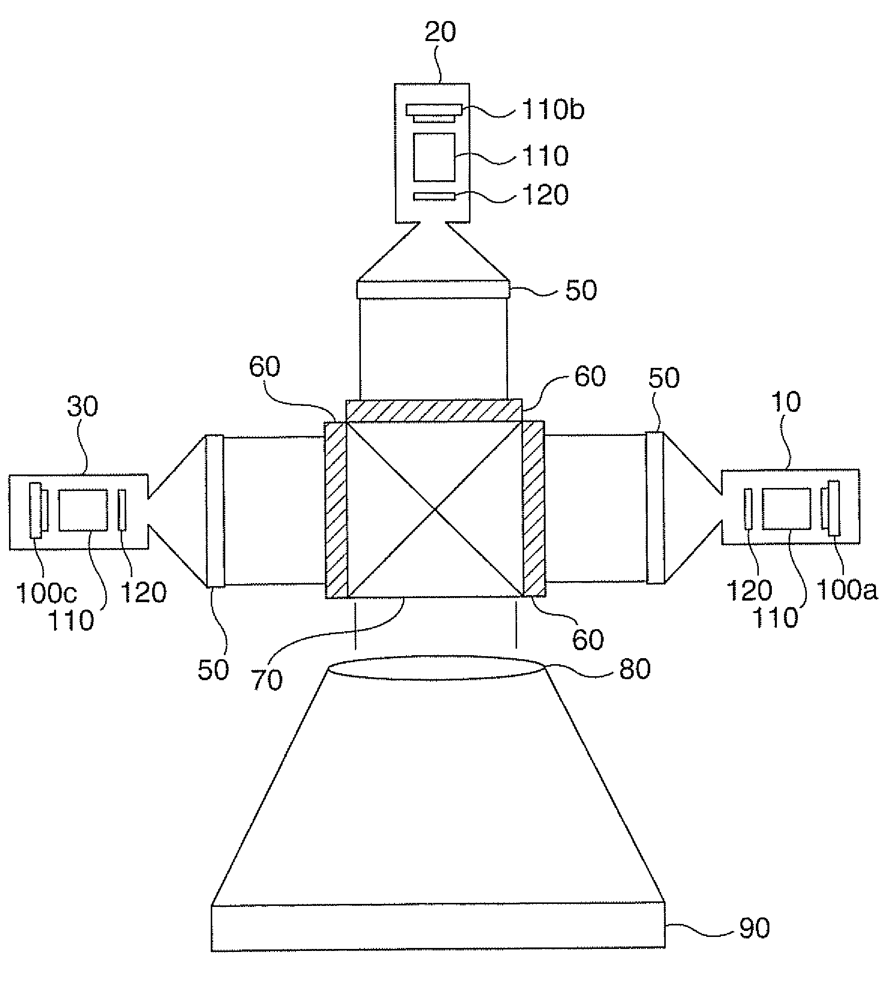
[0052]A projector as an image display device according to a first embodiment of the invention will be explained with reference to FIG. 1. FIG. 1 is an explanatory diagram for exemplifying a schematic configuration of the projector according to the first embodiment.

[0053]As shown in FIG. 1, the projector I 000 is provided with light source devices 10, 20, and 30, equalizing optical elements 50, light valves 60, a cross prism 70, and a projection lens 80.

[0054]The light source devices 10 through 30 are used as the light source of the projector 1000. The light source device 10 outputs a red laser beam with a wavelength of about 650 nm, the light source device 20 outputs a green laser beam with a wavelength of about 540 nm, and the light source device 30 outputs a blue laser beam with a wavelength of about 430 nm. It should be noted that since the laser beam is absorbed by various instruments, the intensity of the light beam output form the sem...

second embodiment

B. SECOND EMBODIMENT

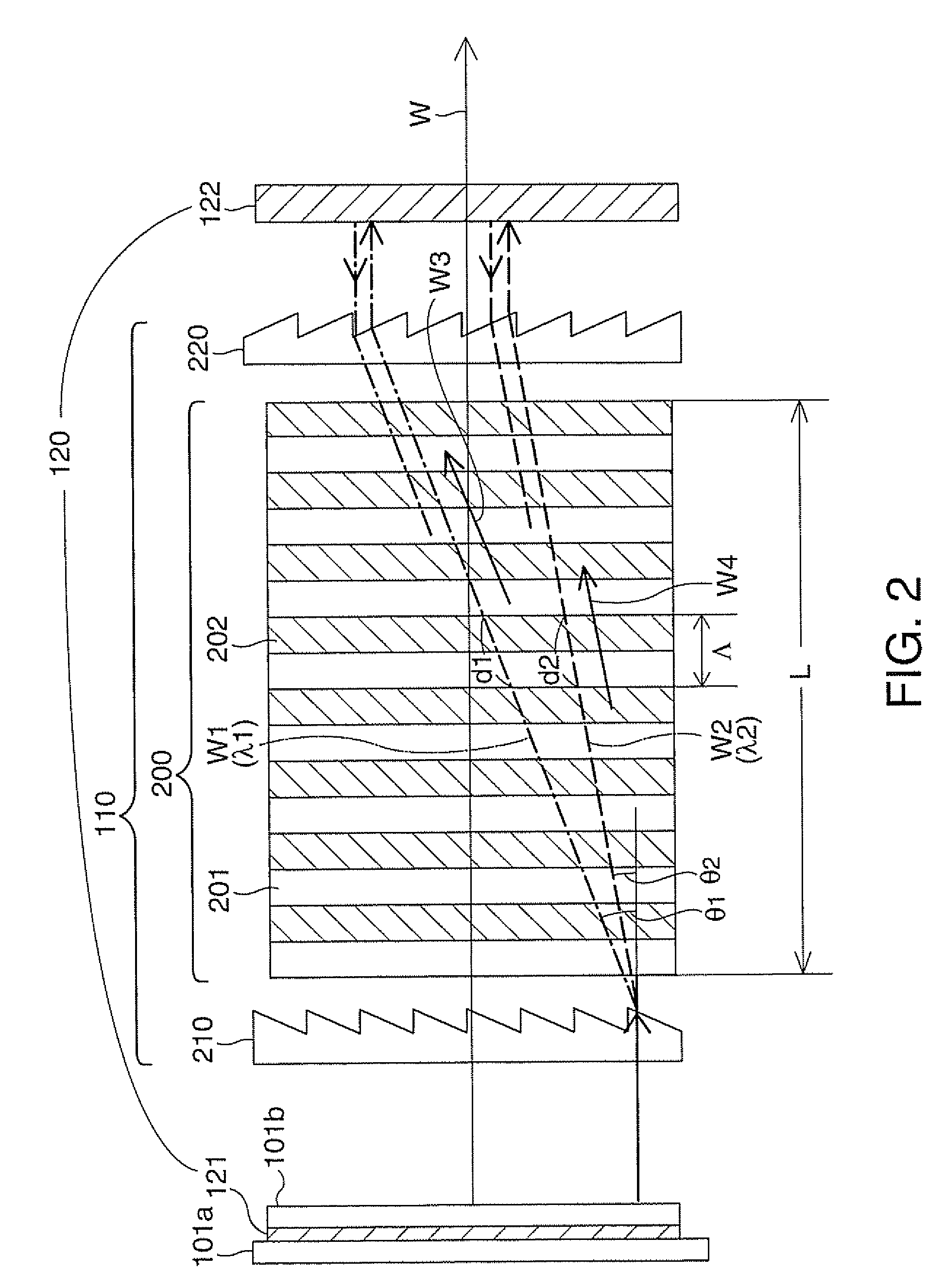
[0086]In the second embodiment, the wavelength conversion element having the diffraction surface provided with the blaze of the transmissive grating disposed facing the second harmonic wave generating element is explained with reference to FIGS. 5 and 6.

B1. Configuration of Wavelength Conversion Element

[0087]FIG. 5 is a schematic diagram for explaining a wavelength conversion element according to the second embodiment. FIG. 6 is a schematic diagram for explaining a structure of the wavelength conversion element according to the second embodiment. The wavelength conversion element 111 of the second embodiment is provided with transmissive gratings 230, 240, and a second harmonic wave generating element 200a. The second harmonic wave generating element 200a has the polarization regions 201 and the polarization inversion regions 202 having polarization directions different from each other.

[0088]As shown in FIG. 6, the transmissive grating 230 is provided with a plur...

third embodiment

C. THIRD EMBODIMENT

[0095]In the third embodiment, the wavelength conversion element is configured using transmissive gratings having a rectangular groove cross-section.

C1. Configuration of Wavelength Conversion Element

[0096]FIG. 7 is a schematic diagram for explaining the wavelength conversion element according to the third embodiment. The wavelength conversion element 112 of the third embodiment is provided with transmissive gratings 250 and the second harmonic wave generating element 200. The second harmonic wave generating element 200 is the same as the second harmonic wave generating element explained in the first embodiment, and consequently, the explanations therefor will be omitted.

[0097]As shown in FIG. 7, the transmissive grating 250 is provided with a plurality of grooves 253 formed on a first surface 251 facing the second harmonic wave generating element 200 at substantially even intervals, and a planar shape on a second surface 252 opposite to the first surface 251. As s...


PUM

PropertyMeasurementUnit
wavelengthaaaaaaaaaa

Abstract

A wavelength conversion element includes a second harmonic wave generating element provided with an entrance surface and an emission surface, a function of converting an incident fundamental wave into a second harmonic wave with a different wavelength and emitting the second harmonic wave, and a cyclic polarization inversion structure configured so as to be able to match a phase of the second harmonic wave in a pseudo manner, and a first wavelength dispersive optical element disposed on the entrance surface side of the second harmonic wave generating element, having a first diffraction surface for diffracting an incident light beam with a diffraction angle increasing in accordance with a wavelength of an incident light beam to disperse the incident light beam by the wavelength of the incident light beam, and for emitting the light beam dispersed in the first diffraction surface towards the second harmonic wave generating element.

Description

[0001]This application claims priority from Japanese Patent Application No. 2007-026376 filed in the Japanese Patent Office on Feb. 6, 2007, the entire disclosure of which is hereby incorporated by reference in its entirety.BACKGROUND[0002]1. Technical Field[0003]The present invention relates to a wavelength conversion element for converting a wavelength using a second harmonic wave generating element, and a light source device, an image display device, and a monitor device using the wavelength conversion element.[0004]2. Related Art[0005]An image display device such as a projector irradiating a spatial light modulator such as a liquid crystal light valve or a digital micromirror device (DMD) with irradiation beams from a light source device to display an image has been used. A laser source device for emitting a laser beam is sometimes used as the light source device.[0006]Some of such laser source devices are each provided with a laser emitting element such as a laser diode and a n...

Claims


Application Information

Patent Timeline
Patent Type & Authority Applications(United States)
IPC IPC(8): G02F1/37G09G3/00
CPCG02F1/3558G02F2203/05G02F2201/17G02F1/37
Inventor KUMAGAI, KEIKOKOMATSU, AKIRA
Owner SEIKO EPSON CORP
Why Eureka
Try Eureka