Path planning and collision avoidance for movement of instruments in a radiation therapy environment

a radiation therapy environment and path planning technology, applied in the field of path planning and collision avoidance for the movement of instruments in the radiation therapy environment, can solve the problems of reducing availability, cost, and system profitability, positioning and registration detracting from the overall patient throughput, and reducing the latency. , to achieve the effect of avoiding collisions, increasing movement efficiency, and reducing latency

Inactive Publication Date: 2008-08-07
LOMA LINDA UNIV MEDICAL CENT
View PDF99 Cites 46 Cited by
  • Summary
  • Abstract
  • Description
  • Claims
  • Application Information

AI Technical Summary

Benefits of technology

[0014]Embodiments of the invention provide a patient positioning system for a therapeutic radiation system having moving components. The patient positioning system pre-plans and analyzes movements to increase movement efficiency for decreased latency and to pro-actively avoid collisions. The patient posit

Problems solved by technology

In particular, a radiation therapy apparatus is an expensive piece of medical equipment to construct and maintain both because of the materials and equipment needed in construction and the indication for relatively highly trained personnel to operate and maintain the apparatus.
As the actual delivery of the radiation dose, once the patient is properly positioned, is relatively quick, any additional latency in patient ingress and egress from the therapy apparatus, imaging, and patient positioning and registration detracts from the overall patient throughput and thus the availability, costs, and profitability of the system.
The movable components of a radiation therapy system also tend to be rather lar

Method used


Image

  • Path planning and collision avoidance for movement of instruments in a radiation therapy environment
  • Path planning and collision avoidance for movement of instruments in a radiation therapy environment
  • Path planning and collision avoidance for movement of instruments in a radiation therapy environment

Examples


Embodiment Construction

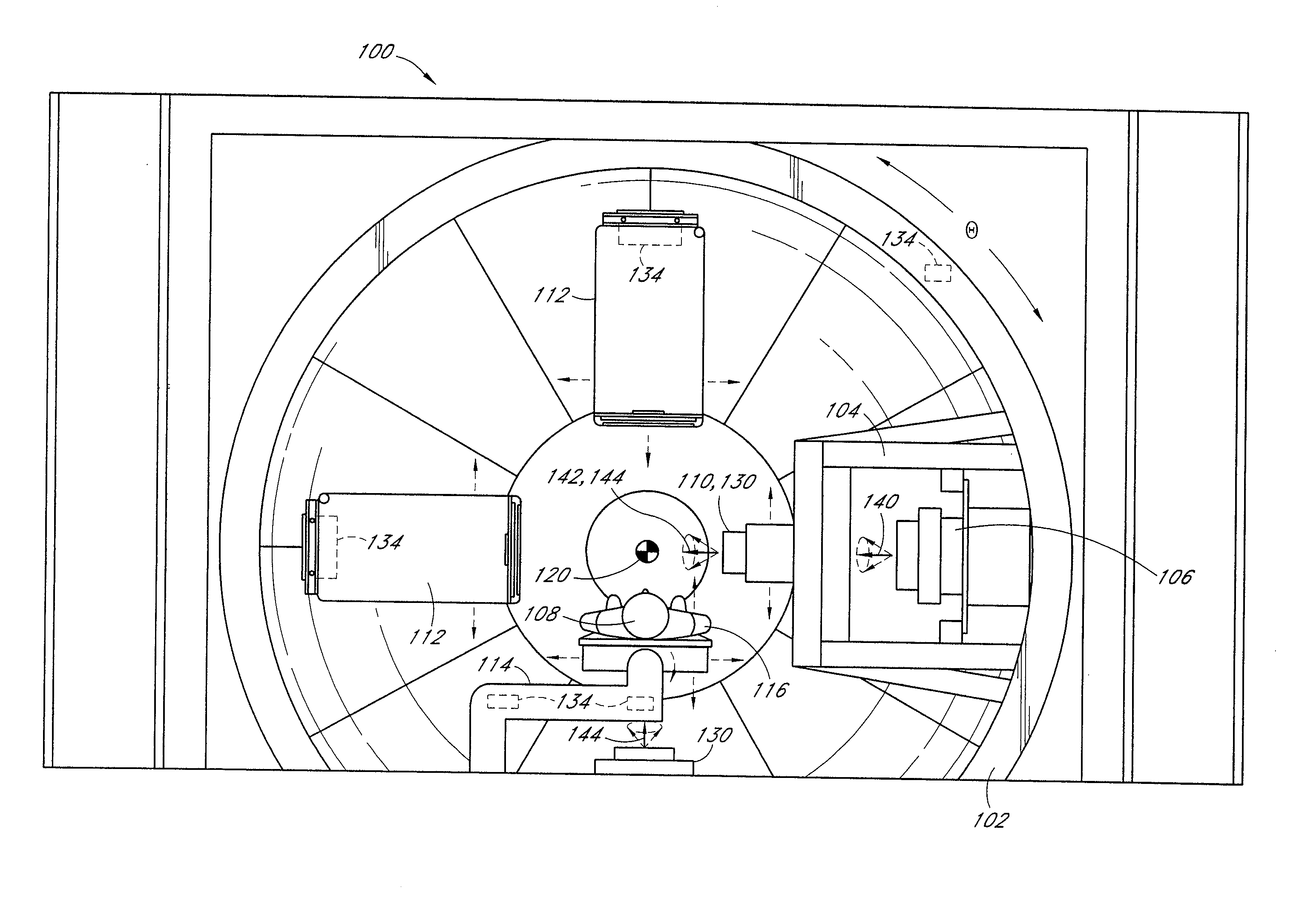
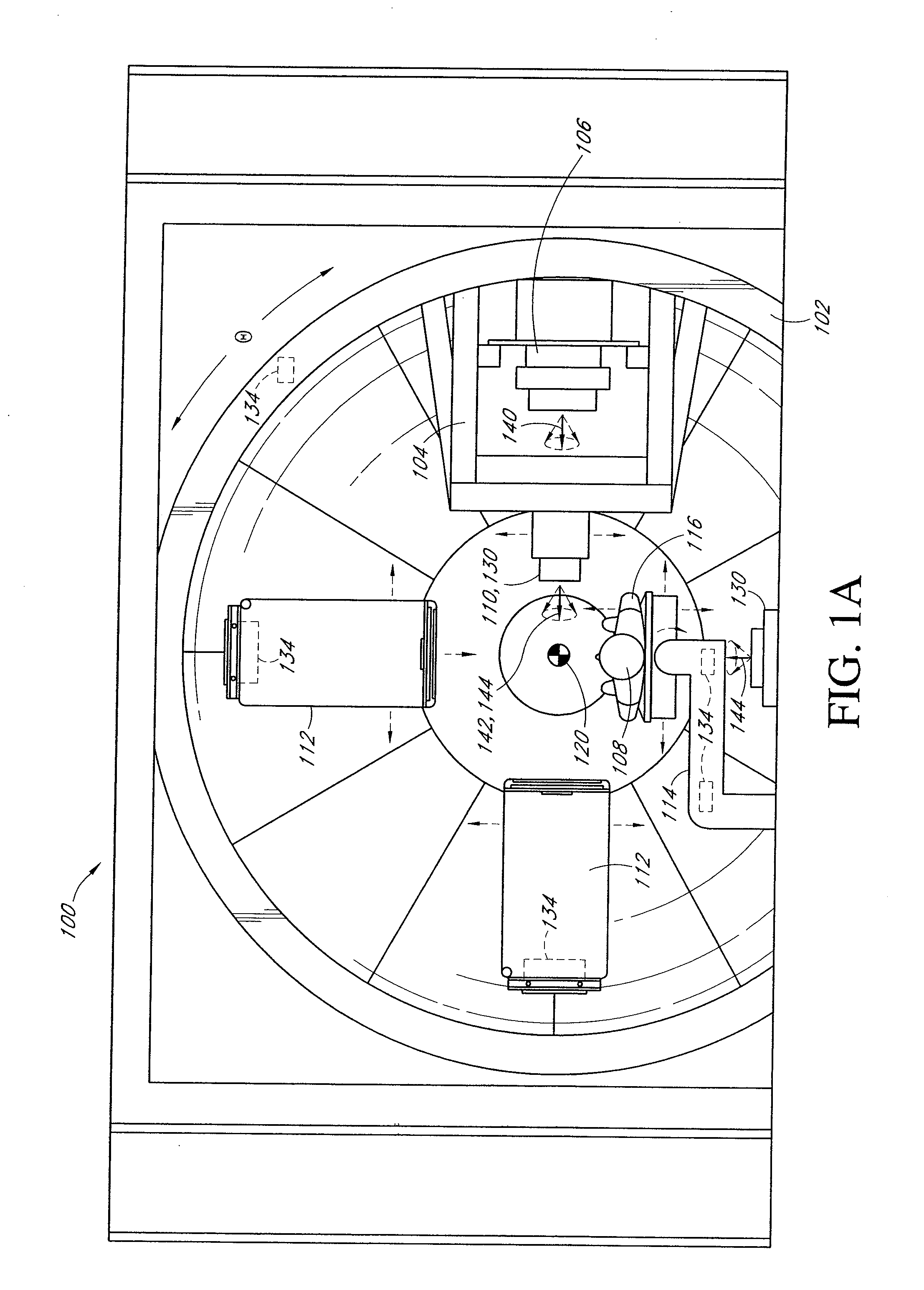
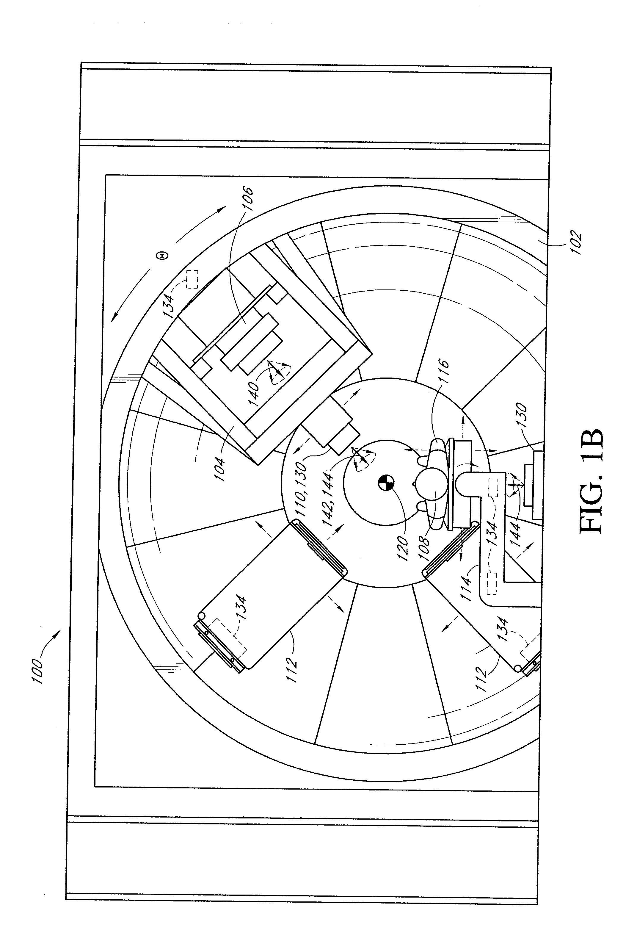
[0034]Reference will now be made to the drawings wherein like reference designators refer to like parts throughout. FIGS. 1A and 1B illustrate schematically first and second orientations of one embodiment of a radiation therapy system 100, such as based on the proton therapy system currently in use at Loma Linda University Medical Center in Loma Linda, Calif. and as described in U.S. Pat. No. 4,870,287 of Sep. 26, 1989 which is incorporated herein in its entirety by reference. The radiation therapy system 100 is designed to deliver therapeutic radiation doses to a target region within a patient for treatment of malignancies or other conditions from one or more angles or orientations with respect to the patient. The system 100 includes a gantry 102 which includes a generally hemispherical or frustoconical support frame for attachment and support of other components of the radiation therapy system 100. Additional details on the structure and operation of embodiments of the gantry 102 ...


PUM


Abstract

A patient positioning system for use with a radiation therapy system that monitors the location of fixed and movable components and pre-plans movement of the movable components so as to inhibit movement if a collision would be indicated. The positioning system can also coordinate movement of multiple movable components for reduced overall latency in registering a patient. The positioning system includes external measurement devices which measure the location and orientation of objects, including components of the radiation therapy system, in space and can also monitor for intrusion into the active area of the therapy system by personnel or foreign objects to improve operational safety of the radiation therapy system.

Description

[0001]RELATED APPLICATIONS[0002]This application is a continuation of U.S. patent application Ser. No. 10 / 917,220, filed Aug. 12, 2004, and claims the benefit of the U.S. Provisional Application No. 60 / 494,699 filed Aug. 12, 2003 and U.S. Provisional Application No. 60 / 579,095 filed Jun. 10, 2004 both entitled “Precision Patient Alignment and Beam Therapy System” and all of which are incorporated in their entireties herein by reference.GOVERNMENT SUPPORT[0003]This invention was made with United States Government support under the DAMD17-99-1-9477 and DAMD17-02-1-0205 grants awarded by the Department of Defense. The Government has certain rights in the invention.BACKGROUND OF THE INVENTION[0004]1. Field of the Invention[0005]The invention relates to the field of radiation therapy systems. One embodiment includes an active path planning and collision avoidance system to facilitate movement of objects in a radiation therapy environment in an efficient manner and so as to proactively av...

Claims


Application Information

Patent Timeline
IPC IPC(8): A61N5/10A61B34/20A61NG01K1/08G21G4/00G21K5/08
CPCA61B6/0442G05B15/02A61N5/1049A61N5/1069A61N5/1078A61N2005/1059A61N2005/1061A61N2005/1062A61N2005/1087A61N2005/1097B25J9/1666G05B2219/45117A61B6/4092A61N5/1067A61B2019/5437A61B2090/3937A61N5/10G01N23/223A61N2005/105A61B6/547A61N5/1037A61N5/107
Inventor CHENG, CHIEH C.LESYNA, DAVID A.MOYERS, MICHAEL F.
Owner LOMA LINDA UNIV MEDICAL CENT
Why Eureka
Try Eureka