Image blur correction apparatus, lens barrel, and image capture apparatus

a technology of image blur correction and lens barrel, which is applied in the direction of printers, instruments, camera body details, etc., can solve the problems of inability to accurately drive and control the moving frame, the device required for setting up the reference position of the moving frame becomes enormous, and the cost increase is considerabl

Inactive Publication Date: 2008-08-07
SONY CORP
View PDF8 Cites 82 Cited by
  • Summary
  • Abstract
  • Description
  • Claims
  • Application Information

AI Technical Summary

Benefits of technology

[0027]The lens barrel of in an embodiment of the present invention includes a cylinder body in which a lens system is accommodated and an image blur correction apparatus having a correction lens for correcting image blurs in the lens system. The image blur correction apparatus for the lens barrel includes a moving frame for holding the correction lens, a support frame for supporting the moving frame through a move guide in a movable manner on a plane orthogonal to an optical axis of the correction lens, a first electric actuator for generating a force to move the moving frame in a first direction orthogonal to the optical axis of the correction lens, a second electric actuator for generating a force to move the moving frame in a second direction which is a direction orthogonal to the optical axis of the correction lens and is also orthogonal to the first direction, and an operation limit mechanism for limiting the moving frame from moving in the first direction and the second direction, and preventing the moving frame from rotating in the limit position.

Problems solved by technology

The issue to be solved is that devices required for setting up the reference position of the moving frame becomes enormous and the costs increase considerably, when the image blur correction apparatus is mounted in the lens barrel and the reference position of the moving frame is set up by using the chart.
However, in the image blur correction apparatus in which the moving frame can move on the plane orthogonal to the optical axis of the correction lens, even if the moving frame is limited from moving in the direction in which the force acts, the moving frame rotates.
Therefore, there is an issue that an error arises in the output of the position detector and it becomes impossible to perform the accurate drive and control of the moving frame (correction lens).

Method used


Image

  • Image blur correction apparatus, lens barrel, and image capture apparatus
  • Image blur correction apparatus, lens barrel, and image capture apparatus
  • Image blur correction apparatus, lens barrel, and image capture apparatus

Examples


first embodiment

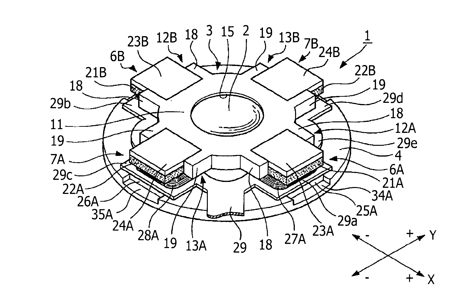
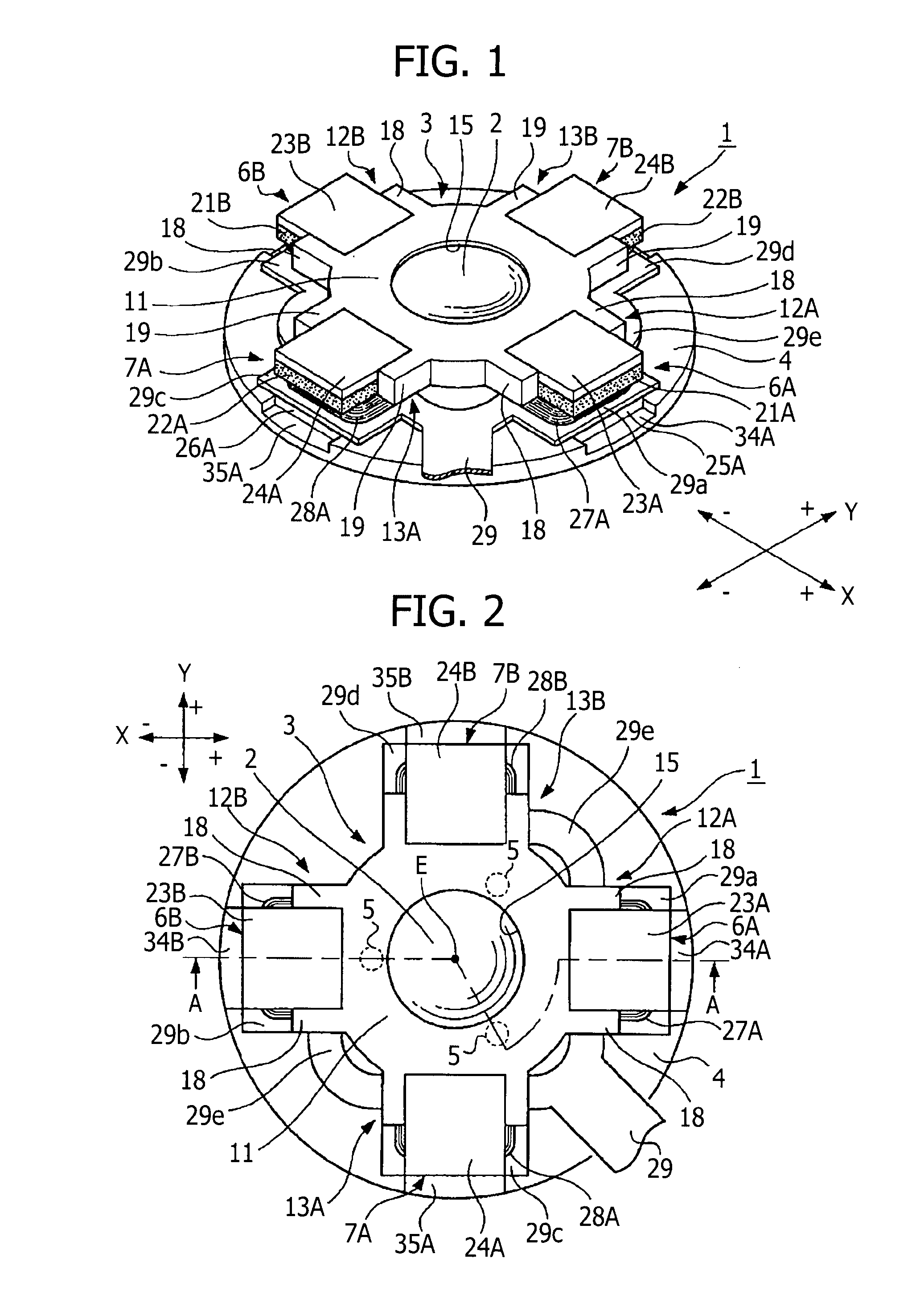
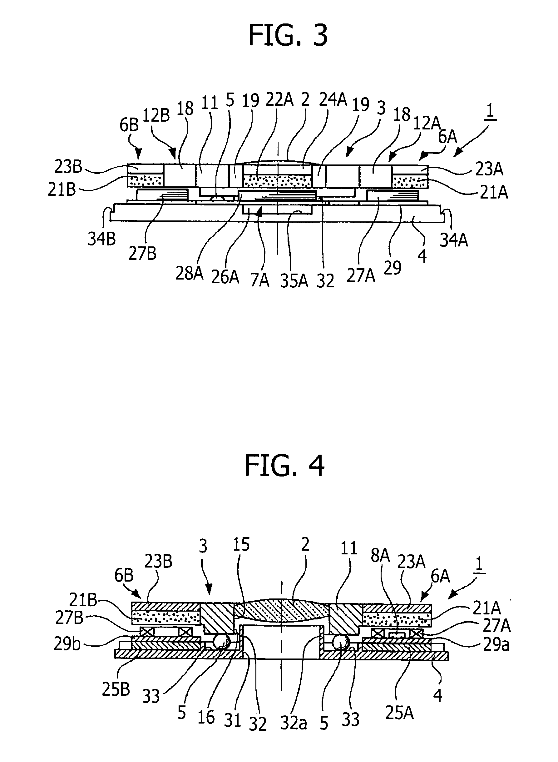
[0071]Hereafter, embodiments of the present invention will be described with reference to the accompanying drawings. FIGS. 1-38 illustrate the embodiments of the present invention. FIG. 1 is a perspective view showing an image blur correction apparatus of the present invention, FIG. 2 is a plan view, FIG. 3 is a front view, FIG. 4 is a sectional view taken along A-A line shown in FIG. 1, FIG. 5 is an exploded perspective view, and FIG. 6 is an illustrative diagram where a state shown in FIG. 5 is viewed from the front side. FIG. 7 is a perspective view illustrating components, FIG. 8 is a perspective view in a state where an undersurface of the moving frame shown in FIG. 7 is turned up, FIG. 9 is a diagram illustrating an arrangement of position detectors in accordance with the image blur correction apparatus of the present invention, FIG. 10 illustrates a position detection mechanism, in which FIG. 10A is a diagram illustrating a schematic structure, and FIG. 10B is a graph showing...

seventh embodiment

[0172]Also in the image blur correction apparatus 1G having such a structure, the reference position of the moving frame 3F can be correctly set like a case in the image blur correction apparatus 1F of the Further, since there are few limits when setting positions of two limit parts 9Ga and 9Gb, it is possible to extend the flexibility of a design. Furthermore, only by bringing two limit receptacle parts 43A and 43B into abutment with two limit projections 45A and 45B, it is possible to stop the moving frame 3F, to carry out positioning unfailingly, and to realize a highly reliable apparatus.

[0173]FIGS. 26A and 26B show the image blur correction apparatus in accordance with the ninth embodiment of the image blur correction apparatus of the present invention, in which FIG. 26A is a plan view and FIG. 26B is a plan view in the state where the moving frame is removed. This image blur correction apparatus 1H has the same structure as that of the image blur correction apparatus 1G of th...

second embodiment

[0236]FIG. 38 is a block diagram showing a schematic structure of the digital still camera provided with the image blur correction apparatus 1 having such a structure and operation as described above. This digital still camera 100A is configured by including the lens barrel 50 having the image blur correction apparatus 1, an image record / reproduction circuit unit 160 which plays the main role of the control apparatus, a built-in memory 161 which has a program memory for driving the image record / reproduction circuit unit 160, a data memory, and other RAM, ROM, etc., an image signal processing unit 162 which processes the captured image etc. into a predetermined signal, a display unit 163 which displays the captured image etc., an external memory 164 for expanding a storage capacity, a correction lens control unit 165 which performs drive control of the image blur correction apparatus 1, etc.

[0237]The image record / reproduction circuit unit 160 is provided with and constituted by, for ...


PUM


Abstract

An image blur correction apparatus includes a correction lens for correcting image blurs in a lens system, a moving frame for holding the correction lens, a support frame for movably supporting the moving frame through a move guide on a plane orthogonal to an optical axis of the correction lens, a first electric actuator for generating a first force to move the moving frame in a first direction orthogonal to the optical axis of the correction lens, a second electric actuator for generating a second force to move the moving frame in a second direction which is a direction orthogonal to the optical axis of the correction lens and is also orthogonal to the first direction, and an operation limit mechanism for limiting the moving frame from moving in the first direction and the second direction, and preventing the moving frame from rotating in the limit position.

Description

BACKGROUND OF THE INVENTION[0001]1. Field of the Invention[0002]The present invention relates to an image blur correction apparatus for correcting image blurs generated by vibration etc. when capturing an image, a lens barrel having the image blur correction apparatus, an image capture apparatus provided with the lens barrel, such as a digital still camera, a video camera, etc.[0003]2. Description of the Related Art[0004]In recent years, there is a remarkable improvement in performance of image capture apparatuses, such as a digital still camera and a video camera, whereby anyone can easily capture a still image and a moving image of high definition and a high performance. Such an improvement in the performance of the image capture apparatus considerably relies on high performances of a lens, imaging devices (CCD, CMOS, etc.), and an image processing circuit.[0005]However, even if the performances of the lens, the imaging device, etc. are improved, when a tremble or a shake arises t...

Claims


Application Information

Patent Timeline
Patent Type & Authority Applications(United States)
IPC IPC(8): G03B17/00
CPCG03B5/00G03B2205/0069G03B2205/0015
Inventor TAKAHASHI, TATSUYUKI
Owner SONY CORP
Why Eureka
Try Eureka