Peristaltic Pump Tube

a technology of peristaltic pump and tube, which is applied in the direction of positive displacement liquid engine, electric/magnetic/electromagnetic heating, prosthesis, etc., can solve the problems of affecting the efficiency of fluid transport, etc., to achieve high flow rate, simple and economical manufacturing, and maintain high level of fluid transport

Active Publication Date: 2008-08-07
GAMBRO LUNDIA AB
View PDF27 Cites 36 Cited by
  • Summary
  • Abstract
  • Description
  • Claims
  • Application Information

AI Technical Summary

Benefits of technology

[0009]An advantage of the invention is that it provides a deformable tube which, used in a peristaltic pump for transport of a fluid, maintains a high level of efficiency of fluid transport, i.e. a high flow rate in relation to the squeeze-and-push action, even after many hours of operation.
[0010]A further advantage is to make available a tube which is simple and economical to manufacture.
[0011]A further aim of the invention is to realise a fluid circuit for medical use, such as for example an extracorporeal blood circuit or a sterile fluid circuit, which is provided with a pump segment that is couplable to a peristaltic pump and which is also able to work, together with the pump, with a high-level performance for a long time.
[0012]In a specific embodiment of the invention, the deformable tube is realized with a PVC resin-based material having a K value, measured according to ISO 1628-2, which is greater than 85, where the K value represents, as is known, an indicative measure of the PVC molecular weight. It has been unexpectedly found that by using a PVC resin of this type for production of deformable tubes fo...

Problems solved by technology

One of the problems of known-type peristaltic pumps consists in the fact that the deformable tube, generally made of a relatively soft plastic material, such as for example plasticated PVC, is prone to considerable wear by effect of the squeezing and sliding pressure it is subjected to by the mobile device, with a consequent degrading of its characteristics, especially its mechanical characteristics, for example its elastic return capacity.
This has a considerable effect on the efficiency of the peristaltic pump over a long use time, causing the fluid flow along the tube to diminish progressively even where the squeezing-pushing action stays the same.
Firstly, the progressive drop in performance of the peristaltic pump considerably limits the work time of the deformable tube. In applications where it is possible to do so, the worn deformab...

Method used


Image

  • Peristaltic Pump Tube
  • Peristaltic Pump Tube
  • Peristaltic Pump Tube

Examples


example

[0040]A deformable tube for a peristaltic pump was manufactured using the following PVC formulation:[0041]100 phr of PVC resin with K of about 100, commercially known as Vinnolit® S 4099;[0042]75.5 phr of DEHA plasticizer;[0043]5.0 phr of ESO co-stabilizer;[0044]1.2 phr Ca / Zn stabilizer;[0045]0.2 phr of lubricant.

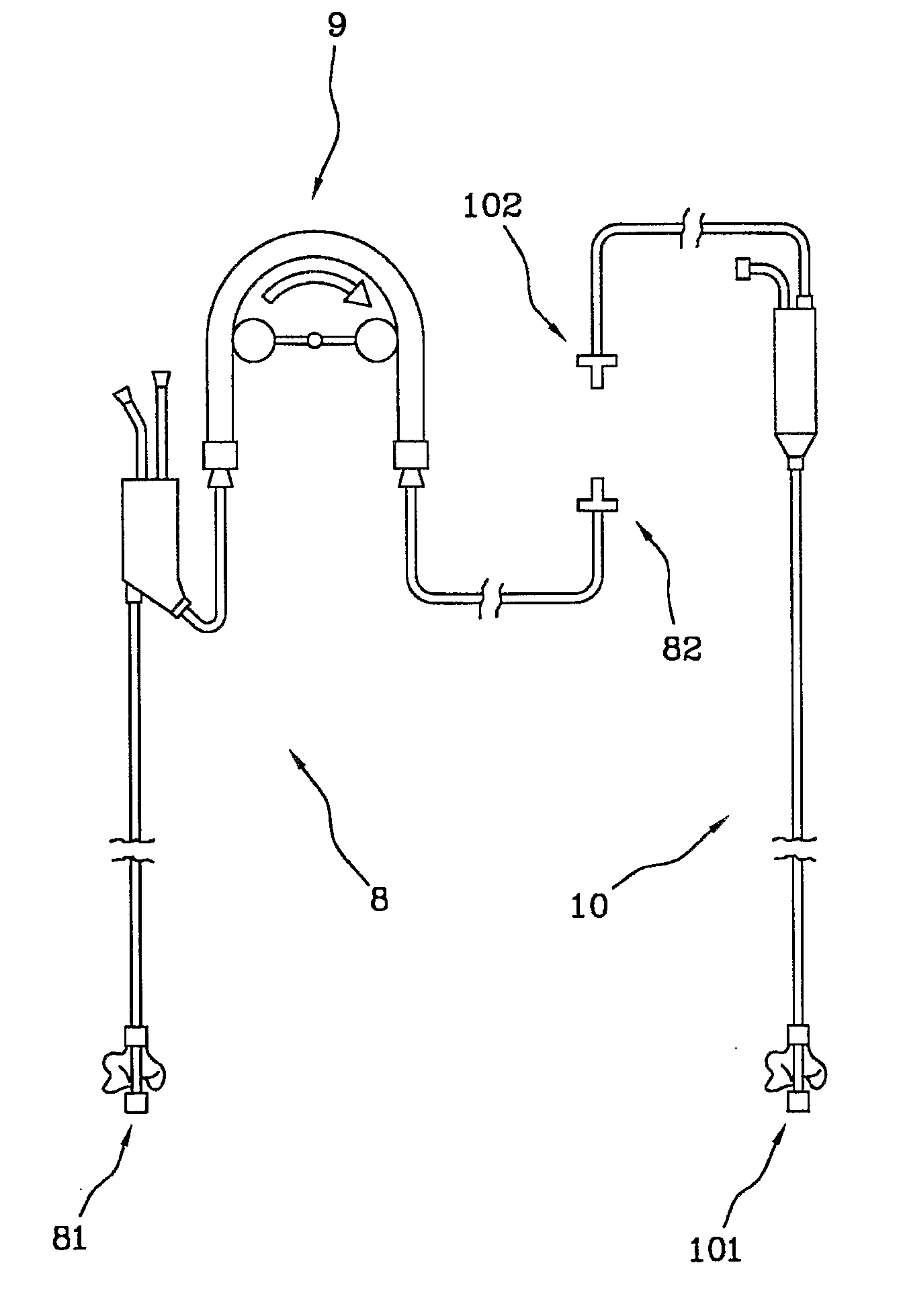
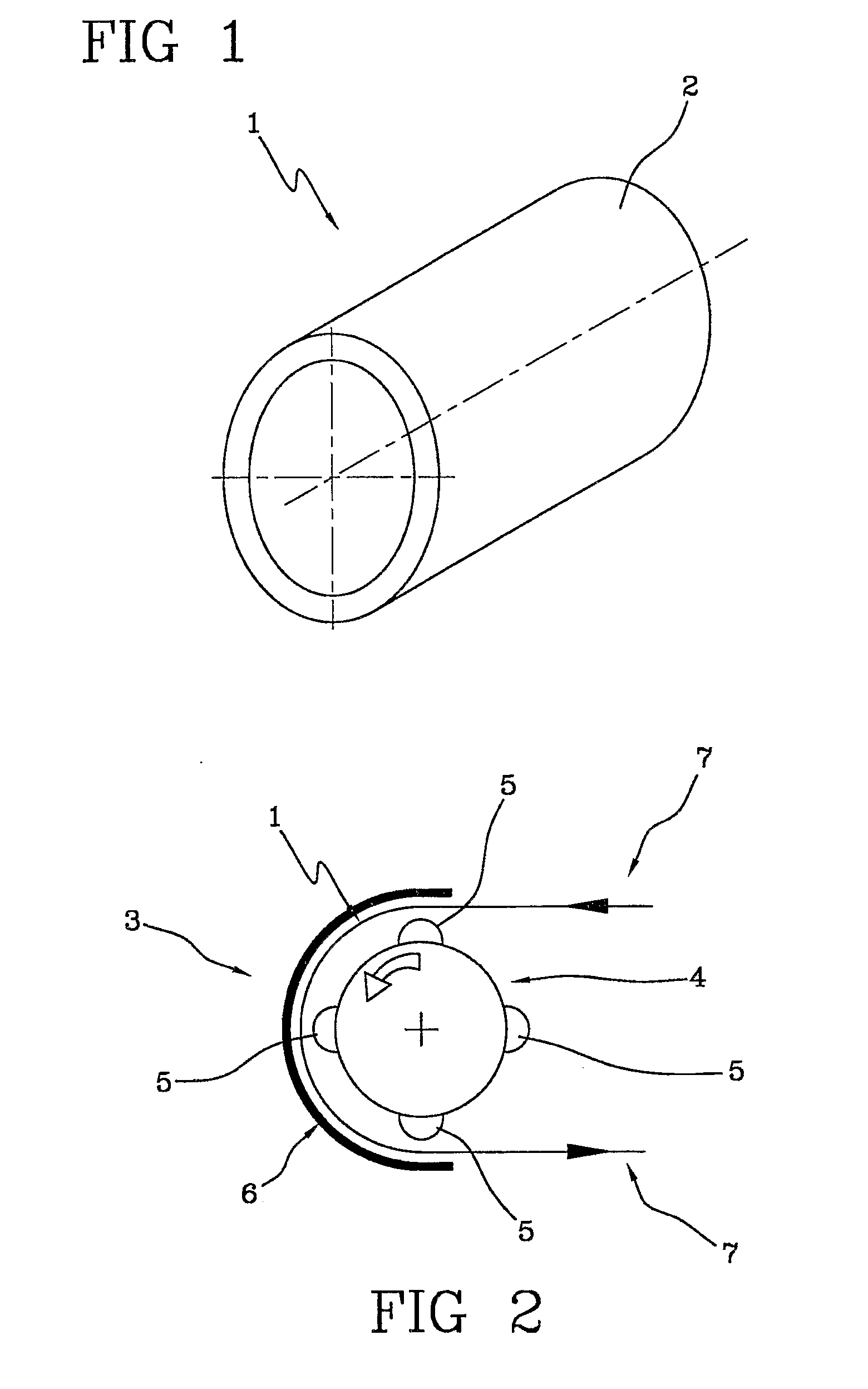
[0046]The tube was made by extrusion of a blend of the above ingredients. The blend was heated to a temperature of between 120 and 150° C. to enable good blending of the various components, after which the resulting dry blend was used for extrusion of the tube. Extrusion temperature for the deformable tube was about 160-180° C. Tube dimensions are those of the tube 1 of FIG. 1. The extruded tube was then sterilized using ethylene oxide and applied together with a rotary peristaltic pump of a dialysis machine for various operational hours.

[0047]The diagram of FIG. 4 shows, on the horizontal axis, the operational time expressed in hours, and on the vertical axis the drop in t...


PUM

PropertyMeasurementUnit
Temperatureaaaaaaaaaa

Abstract

A tube for a peristaltic pump comprises an elastically deformable tubular body (2) made from a PVC composition containing: 100 phr of a PVC resin having a K value, measured according to standard ISO 1628-2, of not less than 85, from 40 to 100 phr of DEHA plasticizer, from 0.05 to 1.0 phr of lubricant, from 0.3 to 15.0 phr of stabilizer and co-stabilizer. The deformable tube, which is usefully employed for liquid transport in a dialysis apparatus, enables a high level of fluid transport efficiency to be maintained, even after many hours of peristaltic pump operation.

Description

BACKGROUND OF THE INVENTION[0001]The invention relates to a tube for a peristaltic pump.[0002]Specifically, though not exclusively, the invention can be usefully employed for transport of a liquid, for example a corporeal fluid (blood) and / or a medical fluid, in a medical apparatus, in particular in an apparatus for extracorporeal blood treatment, such as for example a dialysis apparatus.[0003]The use of deformable-tube peristaltic pumps for transport of liquids is known and widespread. Some examples of deformable tubes used in peristaltic pumps are shown in patent publications U.S. Pat. No. 4,080,113, WO 89 / 04923, WO 95 / 11383, U.S. Pat. No. 5,088,522, EP 0 388 596, U.S. Pat. No. 5,242,279. In a peristaltic pump the tube, which is elastically deformable and contains the fluid to be transported, is squeezed by a mobile device (for example a rotor having at a periphery thereof two or more squeezing rollers) in a zone which progressively advances along the length of the tube so as to p...

Claims


Application Information

Patent Timeline
IPC IPC(8): A61M39/08F04B43/00F04B43/12F04B43/08B29C47/78B29C71/04F16L11/04A61M5/142A61M1/10B29C48/793
CPCF04B43/0072B29C48/793B29C48/832F04B43/00A61M37/00
Inventor GALAVOTTI, FRANCESCAGIANNELLA, CARLO
Owner GAMBRO LUNDIA AB
Why Eureka
Try Eureka