Method For Soldering Composite Material Parts

a composite material and composite material technology, applied in the direction of soldering apparatus, paper/cardboard containers, manufacturing tools, etc., can solve the problems of degrading the quality of the assembly, difficult to braze ceramic matrix composite materials, and uneven brazing composition, etc., to achieve the effect of convenient handling

Inactive Publication Date: 2008-08-14
SAFRAN CERAMICS SA
View PDF22 Cites 28 Cited by
  • Summary
  • Abstract
  • Description
  • Claims
  • Application Information

AI Technical Summary

Benefits of technology

[0006]An object of the invention is to provide a method enabling parts to be assembled together by brazing without the drawbacks mentioned above, in particular enabling the gaseous species produced during heat treatment to be removed and also enabling the thickness of the brazed joint and the contact between said joint and the brazed surfaces to be controlled.
[0008]Thus, the pores in the fiber texture of the pad serve to bring the brazing composition by capillarity over the entire surface covered by the pad, while simultaneously facilitating removal of the gaseous species produced during the rise in temperature.
[0009]In addition, using such a pad makes it possible to control the final thickness of the brazed joint. By selecting the thickness of the pad, it is possible to control the final thickness of the brazed joint in a manner that is reproducible and accurate. Because of its flexibility, the pad also makes it possible to control contact with surfaces for brazing together even when such surfaces present irregularities. This provides continuous contact between the brazed joint and the brazed surfaces, enabling a connection to be obtained between the parts that is uniform and of good quality.
[0012]The pad may be cut to the shapes and sizes of the surfaces of the parts for brazing together. It is easily handled and can be matched to any shape of parts for brazing together. Thus, the zone over which it is desired to form a brazed joint can easily be defined in advance as the zone covered by the pad. It is then possible to make brazed joints that are strong on surfaces of all types, and to do so in a manner that is accurate and reproducible.

Problems solved by technology

Nevertheless, brazing ceramic matrix composite materials is technically difficult.
This lack of material leads to defects in the connection between the two parts and consequently to degraded quality for the assembly, as shown in FIG. 3 which shows the state of a brazed joint obtained by the above-described standard brazing method.
In FIG. 3, it can be seen that the distribution of brazing composition is not uniform because there remain pockets of gaseous species in the brazed joint, thereby weakening the resulting connection.
Nevertheless, even with such improved control over the brazing method, some pockets still remain, leading to defects in the brazed joint.
Furthermore, those brazing techniques do not enable the thickness of the brazed joint to be controlled.
Even with docking planes that have been lapped, the thickness of the resulting brazed joint can vary because of lack of uniformity in the distribution of the brazing composition during the heat treatment.

Method used


Image

  • Method For Soldering Composite Material Parts
  • Method For Soldering Composite Material Parts
  • Method For Soldering Composite Material Parts

Examples


Embodiment Construction

[0024]The method of the present invention for assembling parts together by brazing applies to parts made of any thermostructural ceramic matrix composite (CMC) material, i.e. any material constituted by reinforcement of refractory fibers (carbon fibers or ceramic fibers) densified by a ceramic matrix that is also refractory, such as C / SiC, SiC / SiC, C / C—SiC materials, etc. The method also applies to other types of material that are liable to give off gaseous species during brazing, such as C / C materials or monolithic ceramics.

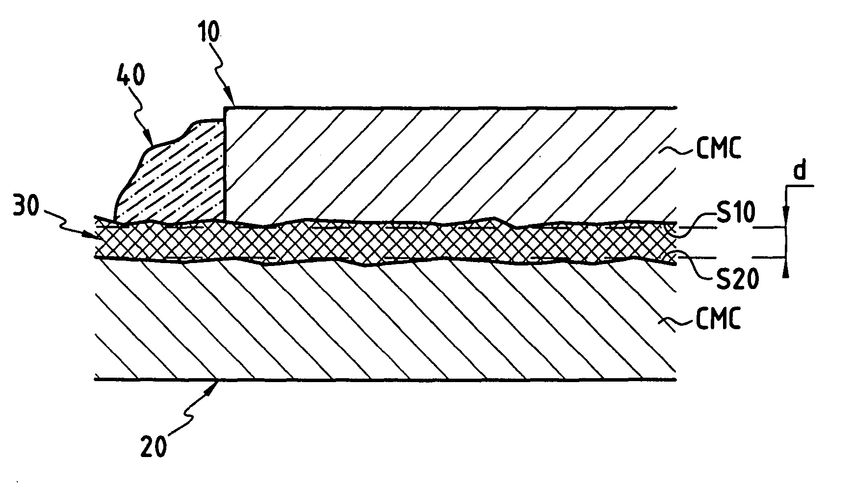
[0025]With reference to FIGS. 5 and 6, an implementation of a method in accordance with the invention for assembling together two parts 10 and 20 of CMC material by brazing comprises the following steps.

[0026]As shown in FIG. 6, the first step (step S1) consists in placing between the surface S10 of a first part 10 of CMC material and the surface S20 of a second part 20 likewise of CMC material, a “dry” (i.e. non-impregnated) pad 30 made of a texture of carbon f...


PUM

PropertyMeasurementUnit
temperaturesaaaaaaaaaa
thicknessaaaaaaaaaa
dimensionsaaaaaaaaaa

Abstract

The invention relates to a method of brazing together two parts (10, 20), the method being characterized in that a pad (30) is interposed between the two surfaces (S10, S20) of the parts that are to be joined together, said pad being formed by a refractory fiber texture, and being at least in part in contact with a brazing composition (40), and heat treatment is performed to liquefy the brazing composition (40) so as to cause the molten brazing composition to be distributed by capillarity over the entire brazing area between the two parts (10, 20) covered by the pad (30).

Description

BACKGROUND OF THE INVENTION[0001]The invention relates to brazing together thermostructural composite materials, and in particular ceramic matrix composite (CMC) materials. CMC materials are typically constituted by a porous substrate, such as a porous fiber substrate, densified by a ceramic matrix. The fibers of the substrate may be carbon fibers or ceramic fibers. The matrix is a refractory ceramic such as, for example, a refractory carbide, nitride, boride, or oxide. CMC materials, such as C / SiC (carbon fiber reinforcement and silicon carbide matrix) composite, for example, are remarkable for their mechanical properties that make them suitable for constituting structural elements, and for their ability to retain these properties at high temperatures.[0002]When making structures out of ceramic matrix composite materials, it is common to build them up from independent elements of CMC material that are assembled together by brazing. Nevertheless, brazing ceramic matrix composite mat...

Claims


Application Information

Patent Timeline
Patent Type & Authority Applications(United States)
IPC IPC(8): B29C65/00B23K31/02B23K1/20B23K1/08C04B37/00
CPCB23K1/08Y10T156/10B23K2203/16C04B37/005C04B2235/428C04B2235/616C04B2237/08C04B2237/083C04B2237/16C04B2237/365C04B2237/38C04B2237/385C04B2237/52C04B2237/55C04B2237/592C04B2237/72Y10T156/1062B23K1/20B23K2103/16B23K1/19
Inventor BOUILLON, ERICJIMENEZ, SEBASTIENTHEBAULT, JACQUES
Owner SAFRAN CERAMICS SA
Why Eureka
Try Eureka