Strip tillage implement

a technology of tillage implements and tillage machines, which is applied in the field of tillage implements, can solve the problems of increasing the problem of residue management, increasing the problem of slicing residue, and the flow capacity of cleaners on conventional strip tillage machines being insufficient, etc., and achieves the effect of compact design, easy adjustment on the go, and increasing the slicing of residues

Active Publication Date: 2008-08-14
DEERE & CO
View PDF20 Cites 27 Cited by
  • Summary
  • Abstract
  • Description
  • Claims
  • Application Information

AI Technical Summary

Benefits of technology

[0009]It is another object of the present invention to provide a single-pass strip tillage machine that is operable in heavy corn stubble and easily adjusted on-the-go, and yet is compact in design.
[0010]A strip tillage machine includes a front-mounted coulter or disk gang with disks spaced on the order of fifteen inches to eliminate need for an extra pass and increase residue slicing. The increased slicing improves residue flow and organic breakdown of the stalks. The gang mounting decreases manufacturing and maintenance costs, and a hydraulic disk depth control system permits independent on-the-go adjustments of applicator tool depth and disk depth. The leading disk gangs may be lifted completely out of ground contact in light residue conditions such as bean stubble. The disk cutting force can be held constant for following ground contour and rocking up over obstacles such as rocks. At the start of a pass, the disks cut stalks before the applicator tool engages the soil so the applicator is always running in cut residue.
[0011]The row cleaner assembly is mounted on parallel links to maintain the proper working attitude of staggered cleaning disks throughout the trip range. The assembly is supported compactly under the rear frame member and provides for easy tool spacing and good trash flow. An adjustment screw and spring assembly applies row cleaner down pressure and allows the cleaner to be adjusted vertically. The structure provides aggressive row cleaning, good trash flow, and protective tripping over obstacles.
[0012]The strip tillage machine includes a closing disk system having a rockshaft with closing disks adjustably mounted at the aft ends of leaf springs. Down-pressure is controlled by a cylinder connected to the rockshaft and to an adjustable hydraulic control valve. Each rockshaft supports a plurality of relatively long closing disk arms. The arms are fabricated from spring steel and may have adjustable mounting locations to change the effective length of the arms and vary the distance between the disks and the applicator tool mounting. Angle adjustment structure also allows the disk blades angles to be varied to make a taller or flatter berm. Cylinder retraction applies down force so that closing disk working depth can be adjusted using a cylinder stop on the rod end of the cylinder. In soil conditions such as loose sand the stop prevents excessive closing wheel depth that would otherwise cause plugging and unsatisfactory berms. In an alternate embodiment, floating closing disks are supported from a beam connected
[0013]A unique mounting bracket connects several components to the machine frame to reduce manufacturing costs and maintain a compact assembly. The mounting bracket accommodates the closing disk rockshaft or the closing disk mounting beam and allows the row cleaners and closing disks to be conveniently mounted and accessed in a relatively small area. In both the floating disk version and the rockshaft version, the closing disk arm lengths are greater than the lengths on most currently available implements so that vertical motion of the disks does not adversely affect disk working angles. By mounting the closing disk arms individually near the forwardmost portion of each unit, severe bending moments on the assembly are reduced, arm flexibility can be increased if desired, and resistance to plugging is increased.

Problems solved by technology

New corn hybrids with taller and stronger stalks increase problems of residue management with the strip tillage practices.
Cleaners on conventional strip tillage machines may not have sufficient aggressiveness and residue flow capacity for the high residue conditions in corn stubble and the like.
Providing an aggressive strip tillage row cleaner assembly with satisfactory trip and residue clearance has been a continuing source of problems.
If the clearing disks fail to remain in a generally level attitude during vertical movement, efficient trash clearing and residue shedding characteristics can be compromised.
In some implements, short closing arms connected by a support located closely adjacent the earthworking tool cause severe twisting moments in the assembly in uneven ground conditions, and trash cannot effectively clear behind the tool causing plugging and slugging.
Short arms adversely affect the working angle of the disks as the closing disks rock vertically.
Often conventional strip tillage machines fail to provide simple adjustments to vary characteristics of the strip till berms such as berm size and berm shape to accommodate varying field conditions on-the-go.
For example, current adjustments may be inadequate if the operator encounters sandy conditions wherein the closing disks operate too deeply and cause plugging and unsatisfactory berms.
Providing a single-pass strip tillage machine that is operable in heavy corn stubble, easily adjusted on-the-go, and compact in design has been a source of difficulty.

Method used


Image

  • Strip tillage implement
  • Strip tillage implement
  • Strip tillage implement

Examples


Embodiment Construction

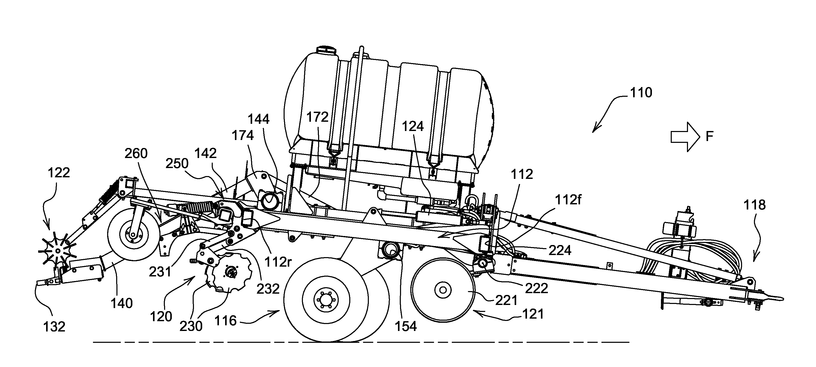
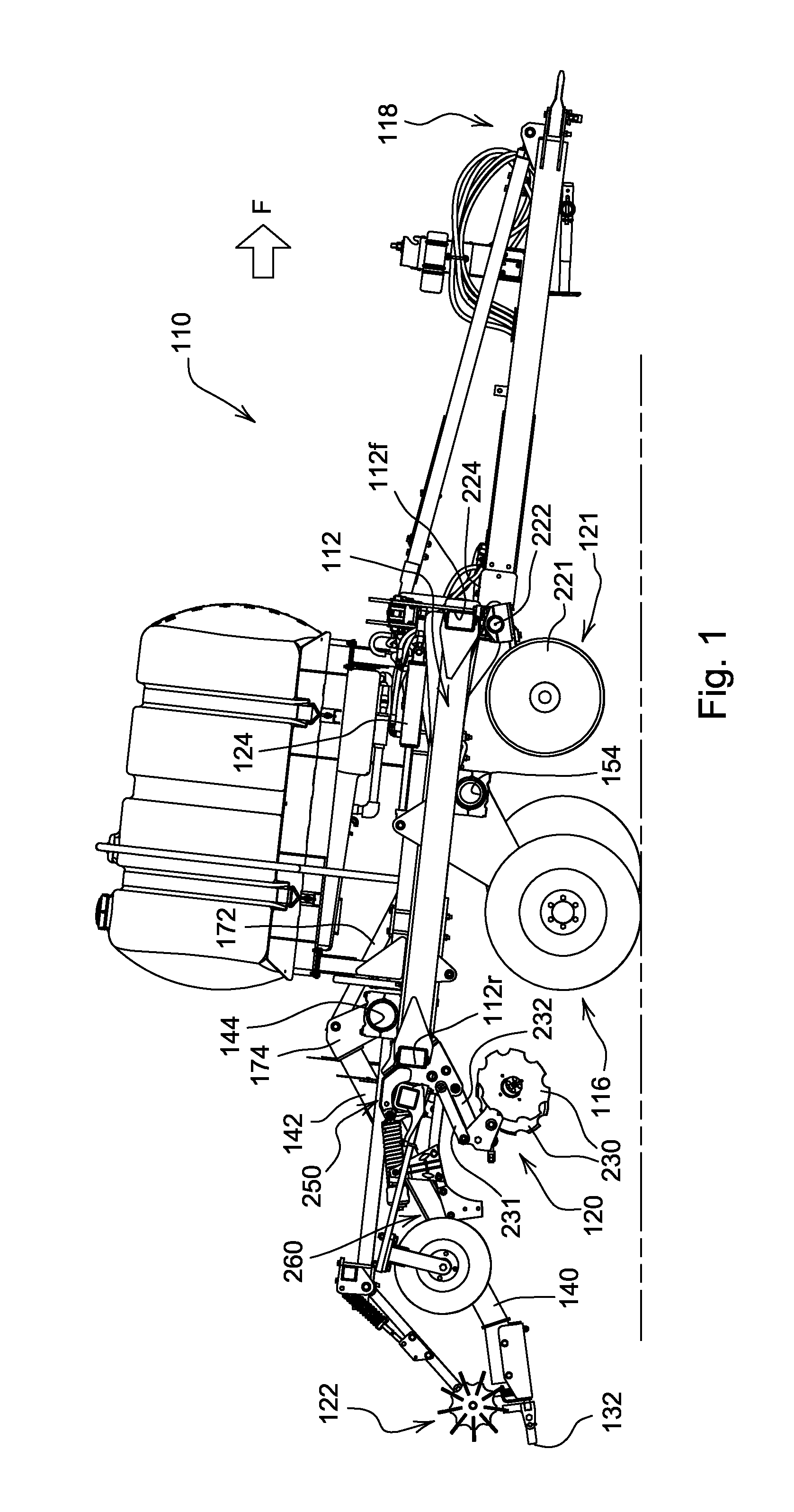
[0022]Referring to FIGS. 1-3, a strip tillage implement 110 includes a main frame 112 supported by lift wheel assemblies 116 for forward movement (F) over the ground. A forward hitch assembly 118 adapted for connection to a towing vehicle (not shown) is attached to the frame 112. The frame 112 supports conventional earth engaging tools and trailing tools indicated generally at 120, 121 and 122 substantially behind a rearmost portion or rear frame member 112r of the main frame 112.

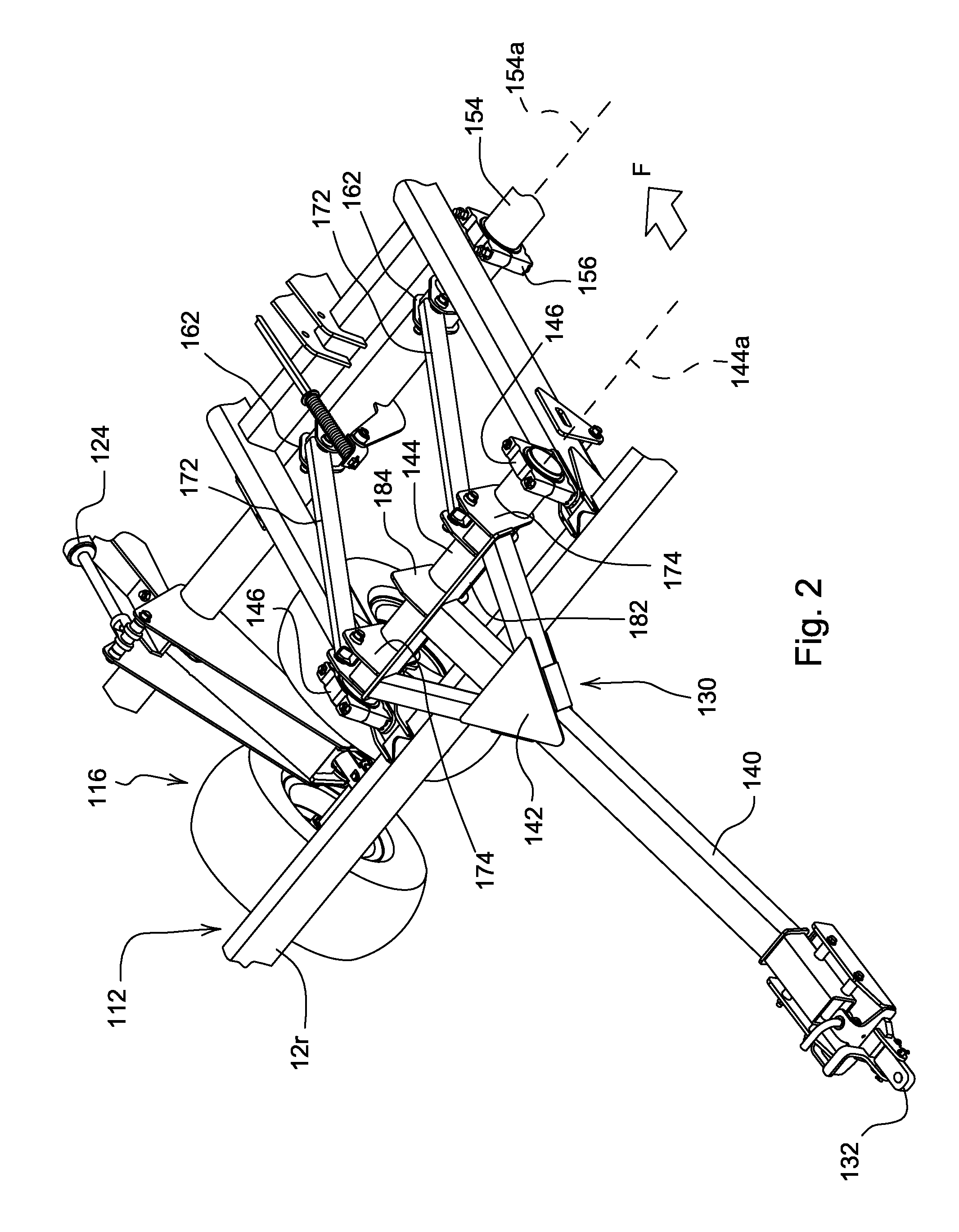
[0023]Hydraulic cylinders 124 operably connected to the lift wheel assemblies 116 raise and lower the frame 112 for moving the implement 110 between a raised transport position (FIG. 1) and lowered field-working positions (FIG. 3). A rear hitch assembly 130 is movably mounted on the main frame 112 and includes a rear connector 132 for towing a trailing implement (not shown) behind the trailing tools 122.

[0024]The rear hitch assembly 130 includes a main hitch beam 140 having a rearwardly and downwardly direc...


PUM


Abstract

A strip tillage implement includes a plurality of forward disk gang members for sizing plant residue. An upright tool support bracket extends rearwardly from the rear frame member and defines a downwardly opening accommodation space at a top portion of the bracket for a closing disk assembly rockshaft or support. The bracket includes a lower end supporting a parallel linkage that carries a clearing tool assembly in a generally constant horizontal attitude as the linkage pivots with movement of the clearing disks over obstacles. A tool support arm is pivotally connected to the bracket adjacent the parallel linkage and below the rear frame member. A closing disk arm supported from the rockshaft can be rotated to adjust down pressure or to lift the closing disk is completely out of ground contact. Closing disk spacing and disk angle are adjustable to provide the desired berm shape. Each closing disk arm is relatively long and independently supported to reduce torsional forces and improve plugging resistance of the units.

Description

[0001]This is a continuation-in-part of our commonly assigned co-pending application Ser. No. 11 / 522,269 filed 15 Sep. 2006 and entitled “Implement Rear Hitch Height and Attitude Control”.FIELD OF THE INVENTION[0002]The present invention relates generally to tillage implements and, more specifically, to strip tillage machines.BACKGROUND OF THE INVENTION[0003]Many growers in the United States are currently switching from conventional tillage methods or minimum tillage methods to zone or strip tillage methods to reduce input costs and increase crop yields. The strip tillage machines currently on the market are designed to perform zone tillage, apply product such as fertilizer, and make a mellow, friable seedbed for the upcoming crop. Residue levels for strip tillage range from light soybean stubble to heavy standing corn stubble.[0004]Individually mounted front coulters are typically used with most conventional strip tillage machines. New corn hybrids with taller and stronger stalks i...

Claims


Application Information

Patent Timeline
Patent Type & Authority Applications(United States)
IPC IPC(8): A01B7/00
CPCA01B21/086A01C5/062A01B49/06A01C7/006Y02P60/20
Inventor STEINLAGE, DAVID L.RUCKLE, JARROD RAY
Owner DEERE & CO
Why Eureka
Try Eureka