Noncontact Data Receiver/Transmiter

a technology of noncontact data and receivers, applied in the direction of electromagnetic bodies, protective materials radiating elements, instruments, etc., can solve the problem of increasing the thickness of ic labels

Inactive Publication Date: 2008-08-14
TOPPAN MOORE CO LTD +1
View PDF22 Cites 19 Cited by
  • Summary
  • Abstract
  • Description
  • Claims
  • Application Information

AI Technical Summary

Benefits of technology

[0024]According to the above constitution, the magnetic microparticles constituting the magnetic substrate layer can form one magnetic body which is linked. Therefore, the relative magnetic permeability of the magnetic substrate layer becomes large, and the magnetic flux passing through the magnetic substrate layer increases, as a result, it becomes easy to generate an induced electromotive force in the antenna which is sufficient for operating the IC chip.
[0026]According to the above constitution, when the non-contact type data reception and transmission body is seen from one surface side of the base substrate, at lease a part of many magnetic microparticles constituting the magnetic substrate layer are overlapped with each other, and one magnetic body which is linked can easily be formed, as a result, the magnetic flux can easily pass through the magnetic substrate layer, and the magnetic flux can easily be picked up by the antenna.
[0028]According to the above constitution, compared with the case in which other magnetic microparticles are used, the magnetic flux can easily pass through the magnetic substrate layer, and the magnetic flux can easily be picked up by the antenna.

Problems solved by technology

Therefore, a problem occurs in which, because the magnetic flux across the antenna of the IC label decreases, and the induced electromotive force decreases, the induced electromotive force is less than the operation electromotive force of the IC chip, and the IC chip does not operate (see for example, Non Patent Document 1: Supervision by Nobuyuki Teraura, “Development and Application of RF tag—Future of Wireless IC chip—”, First edition, CMC Publishing Co., Ltd., Feb. 28, 2003, Page 121, FIG. 2)
On the other hand, in Patent Document 2, a problem occurs in which, because the magnetic core member and the conductive member are provided on one surface of the base substrate, the thickness of the IC label is increased.

Method used


Image

  • Noncontact Data Receiver/Transmiter
  • Noncontact Data Receiver/Transmiter
  • Noncontact Data Receiver/Transmiter

Examples


first embodiment

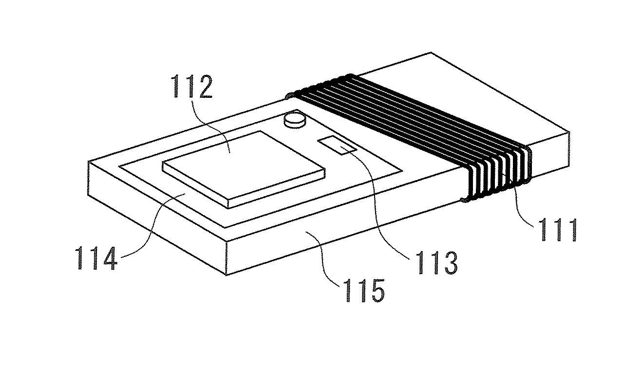
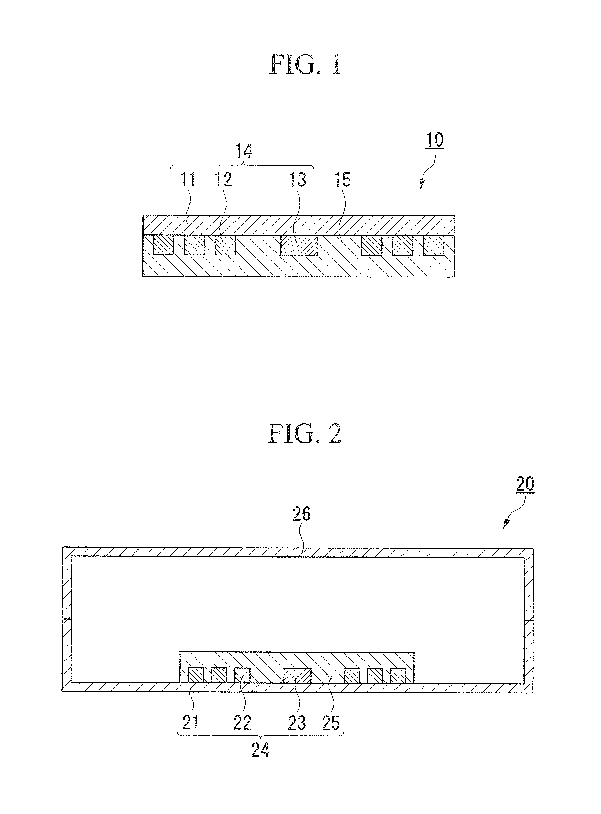
[0036]FIG. 1 is a schematic cross-sectional view showing a first embodiment of a non-contact type data reception and transmission body 10 according to the present invention.

[0037]The non-contact type data reception and transmission body 10 according to the present embodiment is schematically provided with a base substrate 11, an inlet 14 having an antenna 12 and IC chip 13 which are connected to each other, and a magnetic substrate layer 15 disposed so that the magnetic substrate layer 15 covers the antenna 12 and the IC chip 13. Moreover, the magnetic substrate layer 15 is constituted of a complex in which a filler made of at least magnetic microparticles is included in a resin.

[0038]In the non-contact type data reception and transmission body 10, the inlet 14 is provided on one surface of the base substrate 11, that is, the antenna 12 and the IC chip 13, which constitute the inlet 14, are not provided on both surfaces of the base substrate 11, and the antenna 12 and the IC chip 13...

second embodiment

[0087]FIG. 2 is a schematic cross-sectional view showing a second embodiment of a non-contact type data reception and transmission body 20 according to the present invention.

[0088]The non-contact type data reception and transmission body 20 according to the present embodiment is schematically provided with a base substrate 21, an inlet 24 having an antenna 22 and IC chip 23 which are connected to each other, a magnetic substrate layer 25 disposed so that the magnetic substrate layer 25 covers the antenna 22 and the IC chip 23, and a protective member 26 connected to the base substrate 21. Moreover, the magnetic substrate layer 25 is composed of a complex in which a filler made of at least magnetic particulates is included in a resin. Furthermore, the inlet 24 is disposed within a closed space in a casing composed of the base substrate 21 and the protective member 26.

[0089]According to such a constitution, since the inlet 24 is covered, damage thereto can be prevented.

[0090]Hereinaft...

example

[0091]The non-contact type data reception and transmission body as shown in FIG. 1 is manufactured.

[0092]In the present example, in the resin solution in which a saturated polyester resin (specific gravity is 1.1, and glass transition temperature is 15° C.) is resolved in cyclohexanone, magnetic paints produced by adjusting the filler content in the magnetic substrate layer to 30% by weight, 50% by weight, 70% by weight, 75% by weight, and 80% by weight are used, a magnetic substrate layer having a thickness of 200 μm is formed in the non-contact type data reception and transmission body having an aluminum antenna size of 20 mm×60 mm, and thereby five kinds of non-contact type data reception and transmission bodies having different amount of filler in the magnetic substrate layer are manufactured.

[0093]Regarding the five kinds of non-contact type data reception and transmission bodies obtained, magnetic permeability and communication distance at a frequency of 13.5 MHz are measured....


PUM


Abstract

A non-contact type data reception and transmission body has an inlet having a base substrate, and an antenna and an integrated circuit chip which are provided on one side surface of the base substrate, and connected to each other, and a magnetic substrate layer disposed so that the magnetic substrate layer covers at least one of the antenna and the integrated circuit chip which constitute the inlet, wherein the magnetic substrate layer has a main component of a resin including a filler made of magnetic microparticles.

Description

BACKGROUND OF THE INVENTION[0001]1. Field of the Invention[0002]The present invention relates to a non-contact type data reception and transmission body as an information recording media for RFID (Radio Frequency IDentification) use which can receive information from outside and transmit the information outside using electromagnetic waves as a medium.[0003]This application claims priority of Japanese Patent Application No. 2004-368091, filed Dec. 20, 2004, the contents of which are incorporated herein by reference.[0004]2. Description of the Related Art[0005]In recent years, a non-contact type data reception and transmission body as an information recording media for RFID (Radio Frequency IDentification) use such as a non-contact IC (integrated circuit) tag, and the like has been proposed in which information can be received from the outside and can be transmitted to the outside using electromagnetic waves as a medium.[0006]In an IC label, which is an example of the non-contact type...

Claims


Application Information

Patent Timeline
Patent Type & Authority Applications(United States)
IPC IPC(8): G06K19/067
CPCG06K19/07749G06K19/07771H01F1/14791H01F1/28H01Q19/021H01F2038/143H01Q1/2208H01Q1/40H01F2017/048B42D25/22G06K19/07G06K19/077
Inventor KAGAYA, HITOSHIIDE, YOSHIAKIYAMAKAMI, TAKESHIEBIHARA, KENJIWAKE, SHUTARO
Owner TOPPAN MOORE CO LTD
Why Eureka
Try Eureka