System For Delivery Of Reagents From Solid Sources Thereof

a technology for reagents and solid sources, applied in the field of system for delivering reagents from solid sources, can solve the problems of difficult heating of solid sources, sudden bursts of vapor being emitted from solid sources, and the conventional approach to heating solid sources for such vapor generation suffers

Inactive Publication Date: 2008-08-14
ADVANCED TECH MATERIALS INC
View PDF76 Cites 92 Cited by
  • Summary
  • Abstract
  • Description
  • Claims
  • Application Information

AI Technical Summary

Problems solved by technology

Unfortunately, conventional approaches of heating solid sources for such vapor generation suffer from a number of deficiencies.
Typically, it is difficult to heat the solid source material in a manner that will ensure the desired temperature uniformity in the solid mass of source material.
This problem is particularly acute in the case of sublimable solids, in which temperature non-uniformity can lead to sudden bursts of vapor being emitted from the solid.
These bursts in turn create pressure perturbations in the reagent delivery system, and result in less-than-ideal vaporization and mass transport.
For these reasons, improving temperature uniformity of the heated solid is a fundamental challenge in the use of solid source materials.
Another adverse effect of temperature non-uniformity is the occurrence of condensation of vapors in unwanted locations of the process system, such as in transport lines and valves.
Another deficiency in the use of solid source materials is poor heat conduction in loosely packed solids.
In such discontinuous form, the surface-to-volume ratio of the material may be extremely high, and the solid conduction of heat in the particle may be suitable to effect intraparticle heat transfer, but the interstitial voids between particles represent a limiting heat transfer resistance within the overall volume of particles.
Another problem that is encountered in the use of solid source materials is level sensing of the source material in the supply vessel.
Since the supply vessel may be placed in a hot environment or equipped with heating components to facilitate heat conduction from the vessel walls to the solid source material contained in the vessel, the vessel may be constrained by available space or volume limitations that do not permit installation of a level sensing instrument package.
Even if this is not the case, the level sensing instrument package may have associated temperature limitations that are incompatible with the temperatures encountered in heating of the vessel and solid material therein.
A further problem associated with the use of solid source materials is the problem of cleaning and reuse of the supply vessel.
The removal of such solids for reuse of the vessel may be extremely time-consuming, labor-intensive and costly.
Further, the cleaning process may itself introduce additional hazards such as toxicity, pyrophoricity, etc., associated with the cleaning agents that must be used.
As a related consideration in the delivery of low pressure gases and vapors, pressure drop across components of the fluid storage and delivery system, and along flow paths of the fluids, can be a significant issue.
Due to the limited pressure driving force involved in these applications, flow of low pressure fluid reagents is constrained by system components that have excessive pressure drop characteristics.
This circumstance entails potentially severe adverse effects on the downstream fluid-consuming process as well as on products made using the dispensed fluid.
Further, in the dispensing of fluid from vessels in which the fluid is stored on a physical adsorbent medium, the presence of excessive pressure drop in the components associated with a fluid supply vessel imposes a severe restriction on the ability to achieve high utilization of fluid from the vessel.
In subsequent use, such gas is desorbed and dispensed, down to a pressure of 10-20 torr, and thereafter the system is unable to dispense gas at a sufficiently high flow rate.

Method used


Image

  • System For Delivery Of Reagents From Solid Sources Thereof
  • System For Delivery Of Reagents From Solid Sources Thereof
  • System For Delivery Of Reagents From Solid Sources Thereof

Examples


Embodiment Construction

[0059]The present invention relates to a system and process for delivery of reagents from solid sources thereof.

[0060]In a particular aspect, the invention is usefully employed for volatilization of solid source materials for semiconductor manufacturing, including solid sources such as decaborane, octadecaborane, indium chloride, and the like, which are usefully submitted to sublimation in consequence of their low melting points and significant vapor pressures.

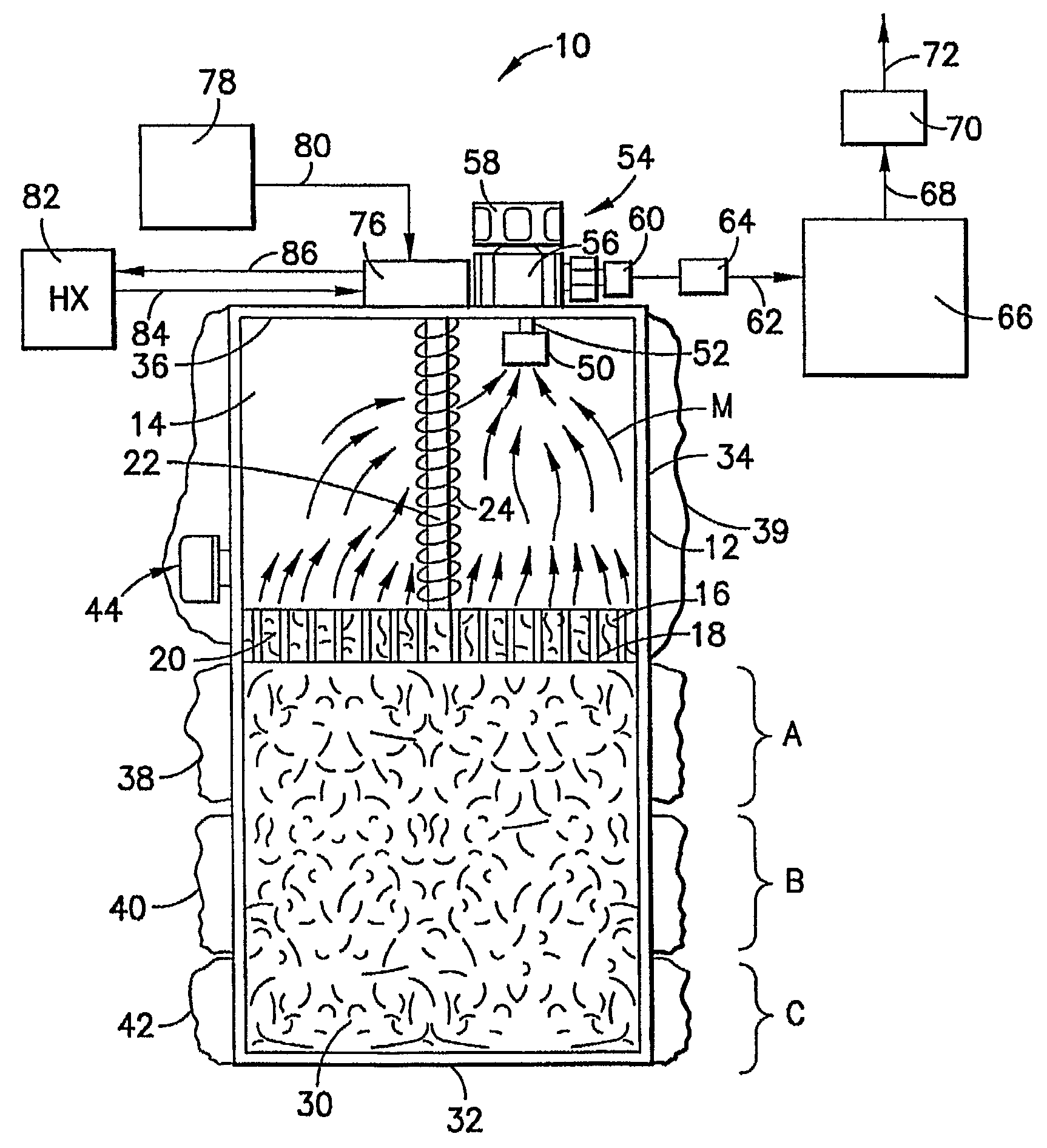
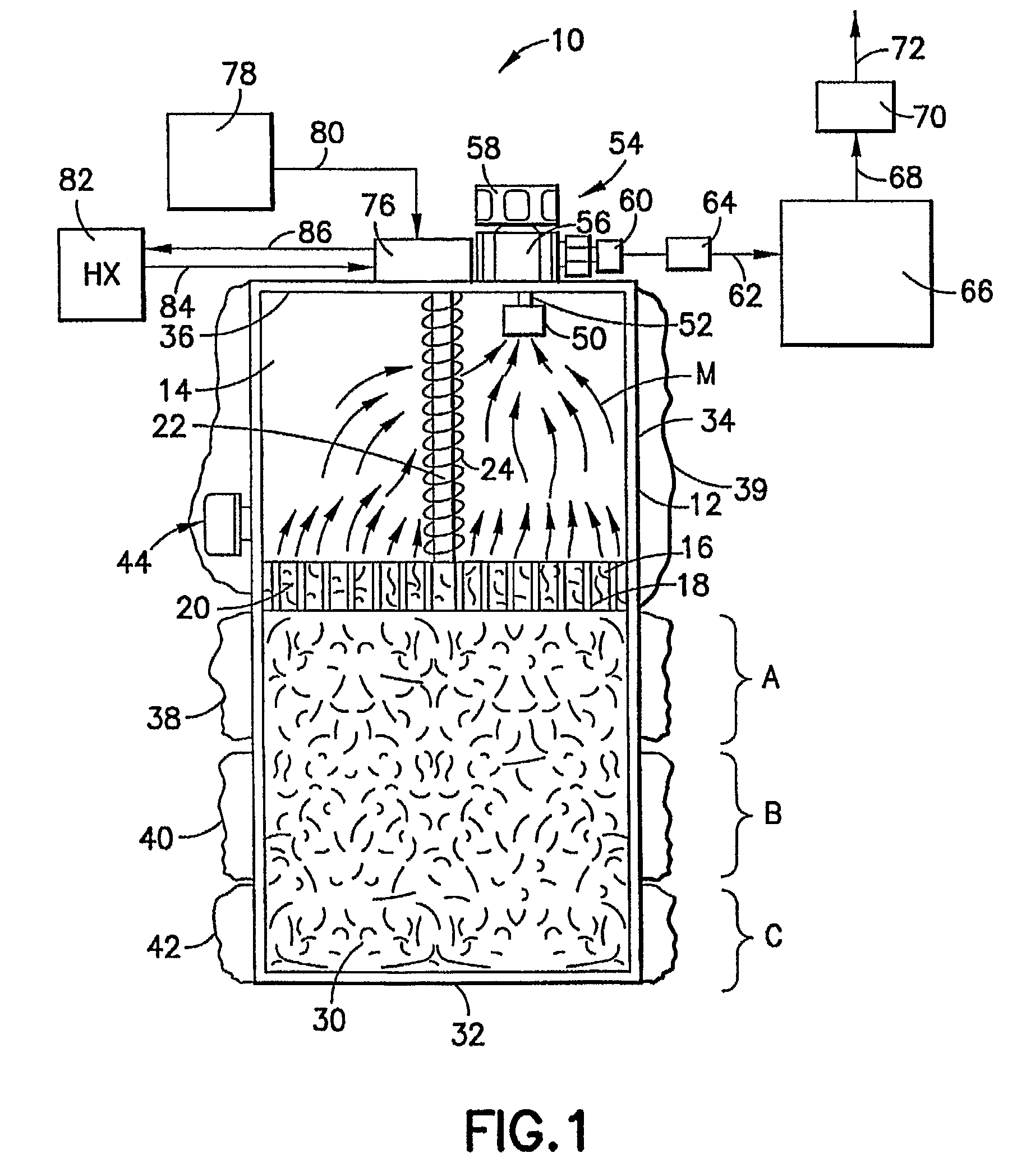
[0061]In many instances, the low pressure production of vapor from solid source materials will require high conductance flow circuitry and components, so that the delivery rate of the volatilized reagent satisfactorily matches the needs of the downstream processing system utilizing such volatilized reagent. In this respect, a particularly useful high conductance flow control valve is shown in FIGS. 25-29 hereof, as described more fully hereinafter.

[0062]Referring now to the drawings, FIG. 1 is a schematic front elevation view ...


PUM

PropertyMeasurementUnit
temperatureaaaaaaaaaa
pressureaaaaaaaaaa

Abstract

A system (10) for delivery of reagent from a solid source thereof, comprising a structure (16, 22, 24) arranged to retain a solid source material (30) in confinement by at least a portion of the structure, for heating and generation of vapor from the solid source material by volatilization thereof, a heat source (82) arranged to heat the solid source material for such volatilization, and a vapor dispensing assembly (52, 54) arranged to discharge the vapor from the system. A high conductance valve (1510) is also described, suitable for use as a dispensing control valve for a reagent storage and dispensing vessel, e.g., a vessel containing a semiconductor manufacturing reagent that is dispensed at low pressure. The high conductance valve includes a valve body (1512) in which inlet and outlet passages are substantially perpendicular to one another, with their interior extremities communicating with a valve chamber (1536) containing a selectively positionable valve element movable between a fully open and fully closed position. Valve flow coefficient (CV) values on the order of 2.7 to 2.9 are achievable by such high conductance valve, enabling the valve to achieve superior dispensing operation even in extremely low pressure regimes, e.g., below 20 torr.

Description

CROSS-REFERENCE TO RELATED APPLICATIONS[0001]The benefit of priority of the following U.S. Provisional Patent Applications is hereby claimed: U.S. Provisional Patent Application No. 60 / 662,515 filed Mar. 16, 2005 in the names of Paul J. Marganski, James I. Dietz and Joseph D. Sweeney for “SYSTEM FOR DELIVERY OF REAGENTS FROM SOLID SOURCES THEREOF” and U.S. Provisional Patent Application No. 60 / 662,396 filed Mar. 16, 2005 in the names of PAUL J. MARGANSKI and JOSEPH D. SWEENEY for “HIGH CONDUCTANCE VALVE FOR USE IN DELIVERY OF LOW PRESSURE FLUIDS.”FIELD OF THE INVENTION[0002]The present invention relates generally to packaging of source reagents and to material delivery systems. In specific aspects, the invention relates to delivery of reagents from solid sources thereof, to corresponding containers for storage and dispensing of source reagents, and to high conductance valves that are useful for the delivery of low pressure fluids, e.g., gases or vapors employed in the manufacture of...

Claims


Application Information

Patent Timeline
Patent Type & Authority Applications(United States)
IPC IPC(8): H01J37/08H01L21/306B08B3/08C23C16/448B08B13/00B08B9/00B01L99/00
CPCB01J7/00B01J19/18B01J2219/00146B01J2219/00141B01J2219/00094C23C14/48C23C14/564C23C16/4405C23C16/4481
Inventor MARGANSKI, PAUL J.DIETZ, JAMESSWEENEY, JOSEPH D.
Owner ADVANCED TECH MATERIALS INC
Why Eureka
Try Eureka