Measurement Method of Non-Circularity of Core Optical Fiber Base Material and Apparatus Therefor

a technology of optical fiber and core, which is applied in the direction of optical apparatus testing, instruments, optical elements, etc., can solve the problems of inability to detect signal light pulses, lack of measurement accuracy, and inability to measure non-circularity of core parts of preforms by the above method, so as to achieve accurate and easy measurement of non-circularity of core parts

Active Publication Date: 2008-08-14
SHIN ETSU CHEM IND CO LTD
View PDF2 Cites 38 Cited by
  • Summary
  • Abstract
  • Description
  • Claims
  • Application Information

AI Technical Summary

Benefits of technology

[0027]According to a measurement method of non-circularity of a core part of an optical fiber base material and an apparatus therefor of the present invention, it is possible to accurately and easily measure non-circularity of a core part of an optical fiber base material.

Problems solved by technology

However, when a core part is not a complete round or distortion is added to the core part in a step manufacturing an optical fiber or an optical cable, the two modes propagating through the optical fiber have a different speed and thus PMD occurs because a symmetric property is broken.
If an influence of PMD becomes large, signal light pulses different from each other are overlapped during optical communication and thus sometimes the detection of signal light pulse becomes impossible.
However, since a diameter of a core part of a single mode optical fiber is extremely small in the order of 10 μm to the utmost, this lacks for measurement accuracy and the measurement of non-circularity is easy to be influenced by a state of a measuring plane when the optical fiber has been cut.
However, non-circularity of a core part of a preform cannot be measured by the above method because the core part is usually synthesized integrally with a part of a clad part.

Method used


Image

  • Measurement Method of Non-Circularity of Core Optical Fiber Base Material and Apparatus Therefor
  • Measurement Method of Non-Circularity of Core Optical Fiber Base Material and Apparatus Therefor
  • Measurement Method of Non-Circularity of Core Optical Fiber Base Material and Apparatus Therefor

Examples


Embodiment Construction

[0055]The invention will now be described based on the preferred embodiments, which do not intend to limit the scope of the present invention, but exemplify the invention. All of the features and the combinations thereof described in the embodiment are not necessarily essential to the invention.

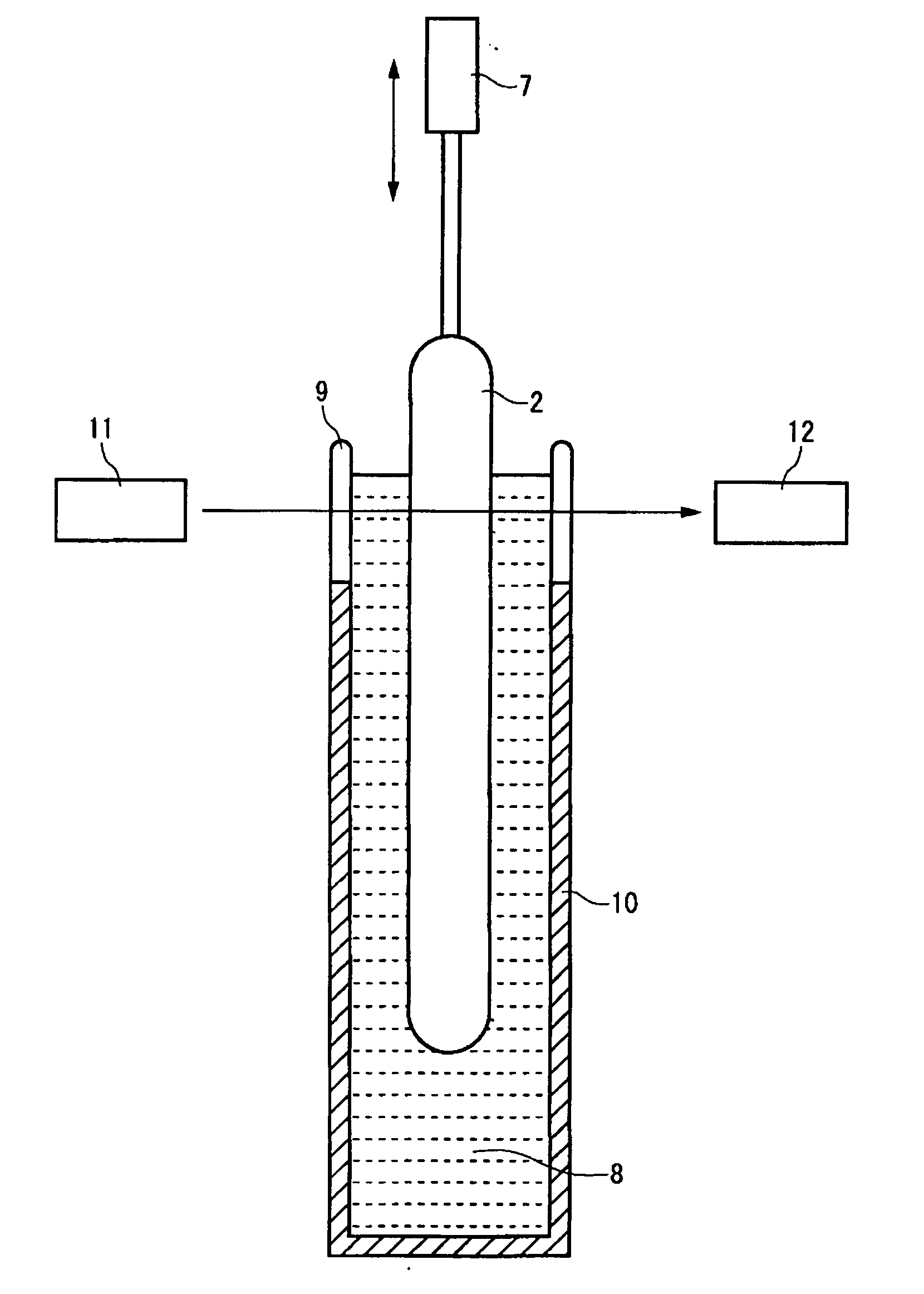
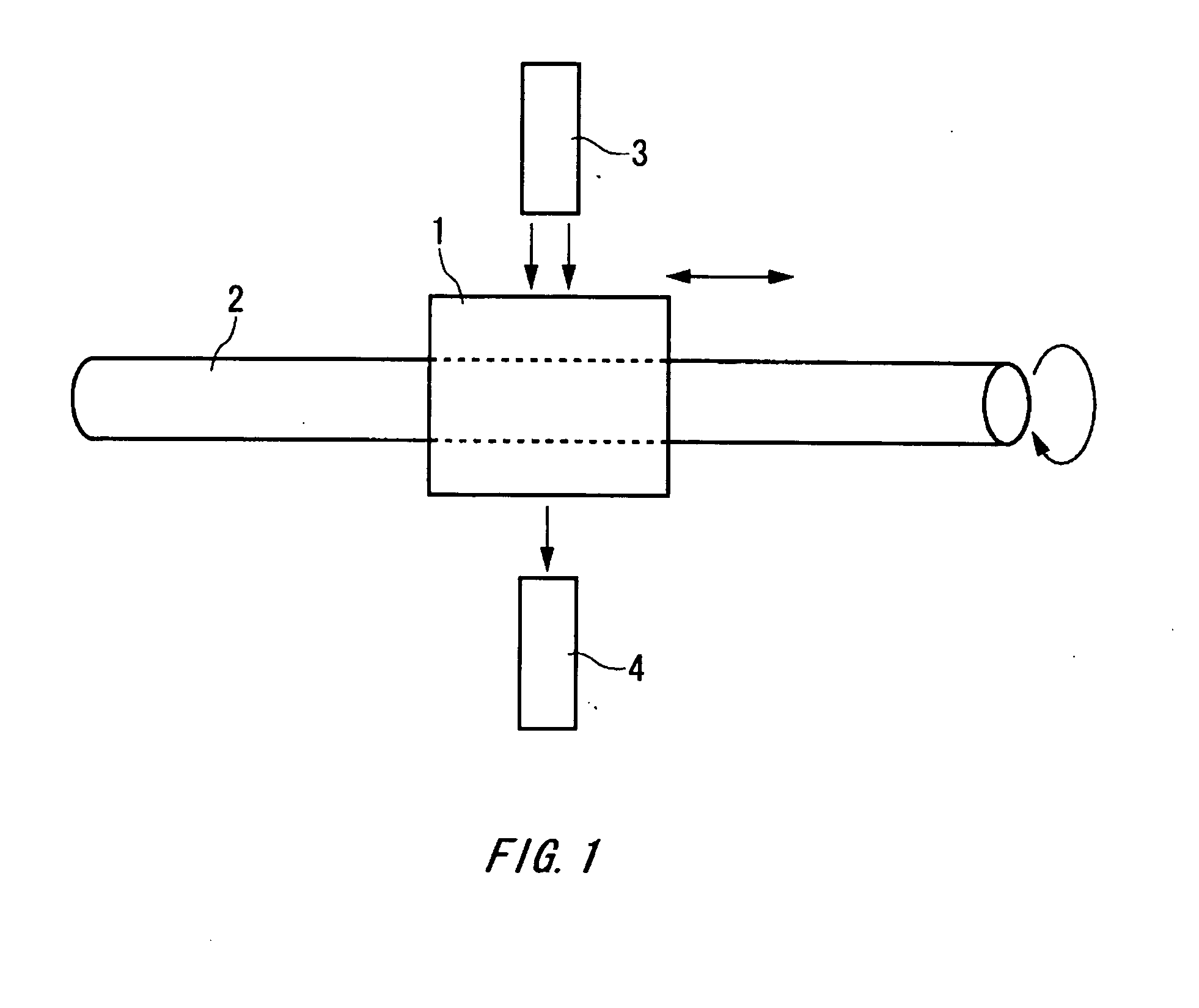
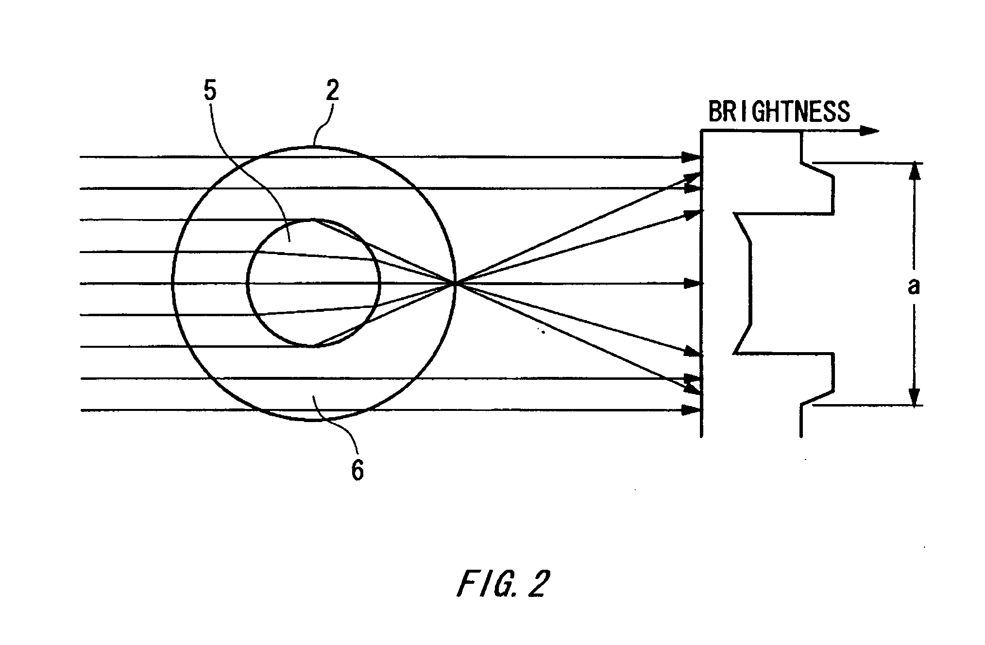
[0056]A measurement method of non-circularity of a core part of the present invention is to irradiate parallel light from a side face of an optical fiber base material, measure a dark space of light intensity distribution in a plurality of circumferential directions φ of the optical fiber base material to obtain a relative value Dc(φ) for a core diameter, and divide a difference between a maximum value and a minimum value of relative values for a core diameter by a mean value of the relative values for a core diameter or calculate 2B / A by means of A and B obtained by fitting Dc(φ) and φ to Dc(φ)=A+Bsin2φ, in order to obtain non-circularity of a core part, and light intensity distribution can ...


PUM

PropertyMeasurementUnit
diameteraaaaaaaaaa
refractive indexaaaaaaaaaa

Abstract

There is provided a measurement method of non-circularity of a core part of an optical fiber base material and an apparatus therefor, which can accurately and easily measure non-circularity of the core part, regardless of a refractive index difference between a core and a clad and an interval between a light projector and a photoreceiver. The method for measuring non-circularity of a core part of an optical fiber base material having the core part and a clad part includes the steps of: immersing the optical fiber base material in liquid having a refractive index substantially equal to that of the clad part of the optical fiber base material; irradiating parallel light from a side face of the optical fiber base material to measure intensity distribution of transmitted light; measuring a width of a dark space caused by light passing the core part on intensity distribution to obtain a relative value for a core diameter; rotating the optical fiber base material to further obtain the relative value for the core diameter at plural points for a circumferential direction; and obtaining non-circularity of the core part based on the obtained plurality of relative values for the core diameter.

Description

TECHNICAL FIELD[0001]The present invention relates to a measurement method of non-circularity of a core of an optical fiber base material and an apparatus therefor.[0002]The present application also relates to the following applications, the contents of which are incorporated herein by reference if applicable.[0003]Japanese Patent Application No. 2004-84718, filed on Mar. 23, 2004[0004]Japanese Patent Application No. 2005-10585, filed on Jan. 18, 2005BACKGROUND ART[0005]In recent years, there has been regarded an influence of polarization mode dispersion (hereinafter, referred to as PMD) as a factor limiting long-distance transmission and speeding up of optical communication. PMD means a phenomenon that two modes having planes of polarization perpendicular to each other propagate through a fiber at a slightly different speed and thus a width of incident pulse enlarges as the incident pulse propagates through the fiber.[0006]A normal single mode optical fiber has a core part and a cl...

Claims


Application Information

Patent Timeline
Patent Type & Authority Applications(United States)
IPC IPC(8): G01N21/00G01B11/30G01B11/08G01B11/24G01M11/00G01M11/02G01M11/08
CPCG01B11/08G01M11/37G01M11/088G01B11/2408G01M11/00G02B6/00
Inventor OTOSAKA, TETSUYA
Owner SHIN ETSU CHEM IND CO LTD
Why Eureka
Try Eureka