Light-amount adjusting apparatus, optical apparatus, and method for manufacturing the light-amount adjusting apparatus

a technology of adjusting apparatus and light-amount, which is applied in the direction of lighting and heating apparatus, semiconductor devices for light sources, instruments, etc., can solve the problems of reducing dimension accuracy, requiring many manufacturing steps for stop blades, and deteriorating optical performance, so as to achieve high dimension accuracy and reduce deterioration. the effect of optical performan

Inactive Publication Date: 2008-08-14
CANON KK
View PDF2 Cites 26 Cited by
  • Summary
  • Abstract
  • Description
  • Claims
  • Application Information

AI Technical Summary

Benefits of technology

[0015]The present invention provides a thin light-amount adjusting apparatus in which light-amount adjusting blades have high dimension accuracy and deterioration of the optical performance is reduced, an optical apparatus including the same, and a method for manufacturing the light-amount adjusting apparatus.

Problems solved by technology

Thus, the stop blade needs many manufacturing steps, and the manufactured stop blade includes a problem in reliability.
However, in the method for manufacturing the stop blade disclosed in Japanese Patent Laid-Open No. 6-317826, flow of resin for injection molding worsens as the thickness of the stop blade is reduced, thereby causing defects that dimension accuracy is reduced or a burr is easily generated on a peripheral portion of the stop blade.
In contrast, a burden for driving the stop blade is increased as the thickness of the stop blade is increased, which increases the size of the aperture stop apparatus in its thickness direction.
Moreover, a step formed between the stop blade and the aperture becomes larger when the thickness of the stop blade is increased, which causes a so-called small-aperture diffraction that deteriorates optical performance.
In addition, light entering a thin translucent burr is refracted at an unexpected angle, thereby resulting in unnecessary light.
Moreover, when the burrs on the stop blades make contact with each other in the assembling or operation of the aperture stop apparatus, the burrs may be removed from the stop blade to generate dust.

Method used


Image

  • Light-amount adjusting apparatus, optical apparatus, and method for manufacturing the light-amount adjusting apparatus
  • Light-amount adjusting apparatus, optical apparatus, and method for manufacturing the light-amount adjusting apparatus
  • Light-amount adjusting apparatus, optical apparatus, and method for manufacturing the light-amount adjusting apparatus

Examples


embodiment 1

[0046]FIG. 8 shows an interchangeable lens apparatus 500 including a light-amount adjusting apparatus that is Embodiment 1 of the present invention. The interchangeable lens apparatus 500 is detachably mounted to an image-pickup apparatus (not shown) such as a digital still camera and a video camera.

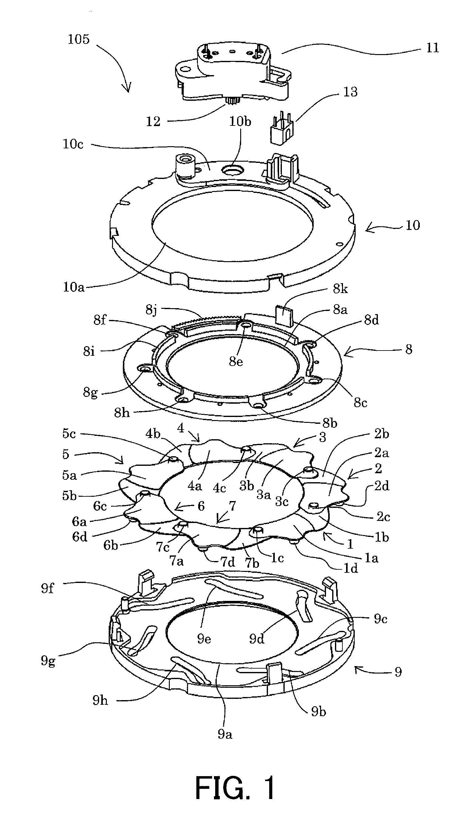
[0047]In the interchangeable lens apparatus (optical apparatus) 500, reference numerals 501, 502, 503, 504 and 505 respectively denote a first lens unit to a fifth lens unit. Reference numeral 105 denotes an aperture stop unit serving as the light-amount adjusting apparatus, which is disposed between the second lens unit 502 and the third lens unit 503.

[0048]The first lens unit 501 to the fifth lens unit 505 that constitute an image-pickup optical system form an object image on the image-pickup element such as a CCD sensor and a CMOS sensor provided in the image-pickup apparatus. The image-pickup element generates an image by photoelectrically converting the object image.

[0049]The apertu...

embodiment 2

[0084]With reference to FIG. 18, an interchangeable lens (optical apparatus) in which an aperture stop unit (light-amount adjusting apparatus) that is Embodiment 2 of the present invention is provided will be described.

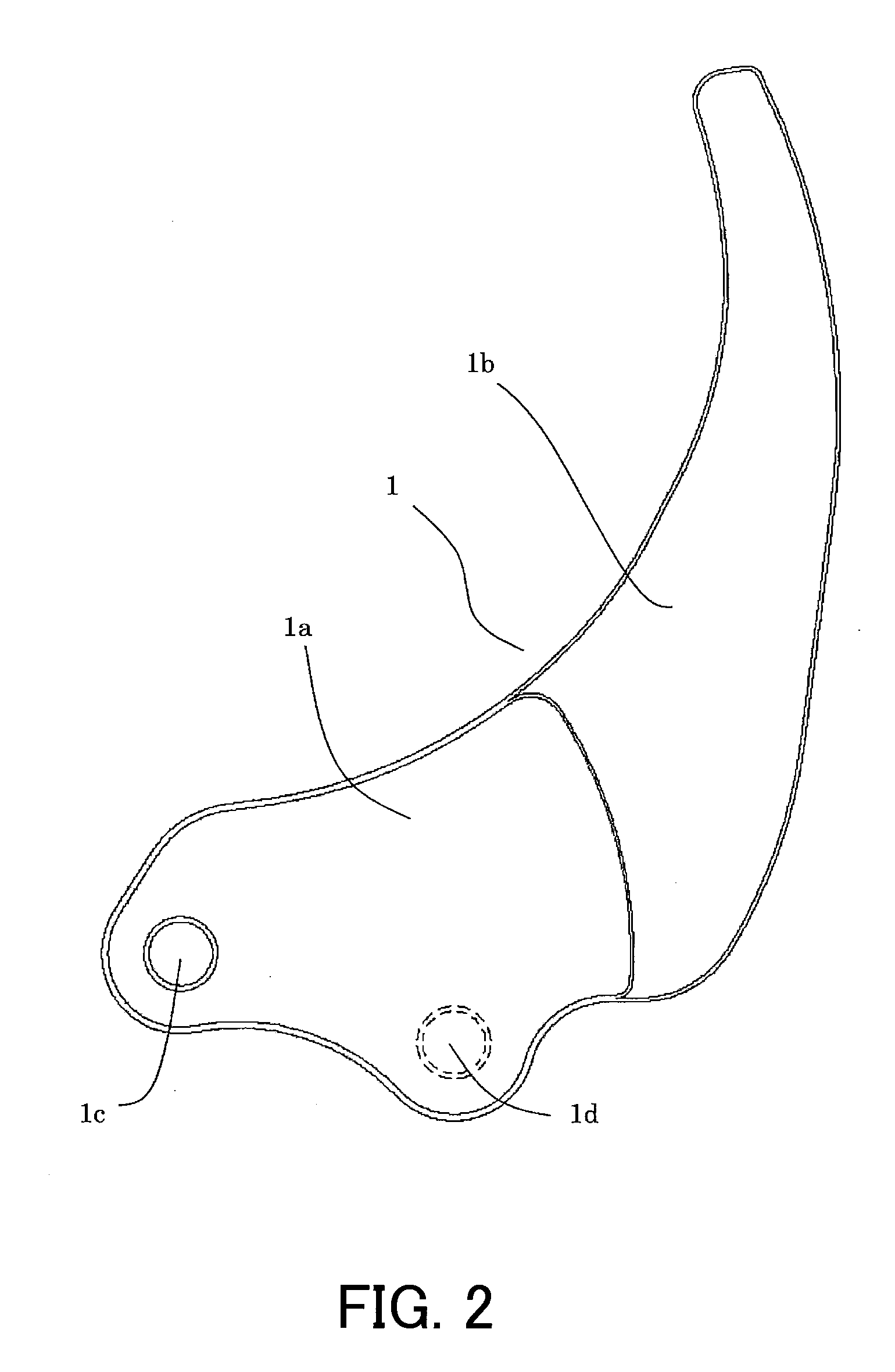
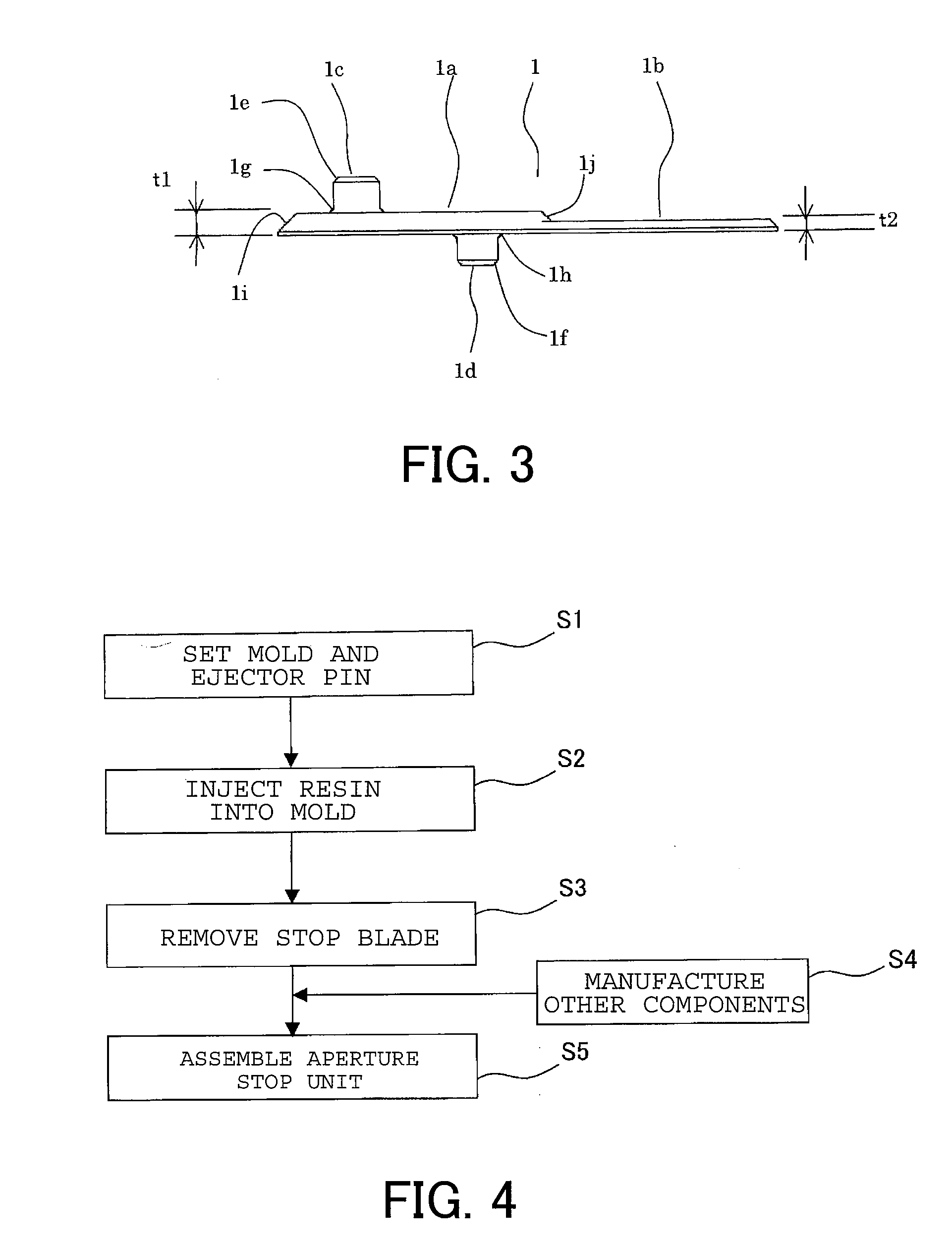
[0085]In the interchangeable lens 300, reference numerals 301 to 305 respectively denote a first lens unit to a fifth lens unit. Reference numeral 307 denotes an aperture stop unit. In the interchangeable lens 300, the aperture stop unit 307 is disposed between the second lens unit 302 and the third lens unit 303. The aperture stop unit 307 includes a plurality of stop blades (light-amount adjusting blades) 21 to 27, each being integrally formed by resin molding.

[0086]Reference numeral 308 is a mount with which the interchangeable lens 300 is mounted to a camera (not shown).

[0087]In the interchangeable lens 300, for the aperture stop unit 307, a first lens unit side is an object side, and a mount side is an image side (image-pickup element side).

[0088]Next, the config...

embodiment 3

[0126]Next, an image-pickup system that is Embodiment 3 of the present invention will be described, the image-pickup system being constituted by the interchangeable lens including the aperture stop unit 105 or 307 described in the above Embodiments 1 or 2 and a camera on which the interchangeable lens is detachably mounted with reference to FIG. 19. Here, the image-pickup system will be described which is constituted by the interchangeable lens 300 including the aperture stop unit 307 described in Embodiment 2 and the camera on which the interchangeable lens 300 is detachably mounted. However, the interchangeable lens 500 including the aperture stop unit 105 described in Embodiment 1 may be used in stead of the interchangeable lens 300.

[0127]The camera 200 is provided with a power switch 203, a release switch 204 and a camera CPU 201. The interchangeable lens 300 is provided with a lens CPU 301, a focus drive unit 306 and the aperture stop unit 307.

[0128]The camera CPU 201 is consti...


PUM


Abstract

A light-amount adjusting apparatus includes a plurality of light-amount adjusting blades that causes a size of a light-passing aperture to change by rotation thereof. Each of the light-amount adjusting blades includes a base portion on which a rotation center portion and a driven portion are formed, and a blade portion that overlaps another light-amount adjusting blade in a light-passing direction so as to form the light-passing aperture. A thickness of the blade portion is thinner than that of the base portion. When the plurality of light-amount adjusting blades is rotated to set the light-passing aperture to be smaller than a full-opened aperture, a thickness of a portion that overlaps an adjacent stop blade is thinner than that of a portion that does not overlap the adjacent stop blade in each of the light-amount adjusting blades. The blades have high dimension accuracy, and deterioration of the optical performance of the apparatus is reduced.

Description

BACKGROUND OF THE INVENTION[0001]The present invention relates to a light-amount adjusting apparatus used for optical apparatuses such as an interchangeable lens, a video camera, a digital still camera and a projector.[0002]Cameras and interchangeable lenses are provided with an aperture stop apparatus (light-amount adjusting apparatus) whose aperture diameter can be changed to adjust a depth of field and a light amount reaching on an image-pickup plane of the image-pickup element, a film or the like. Many projection optical systems of projectors that project light from an image modulation element such as a liquid crystal panel are also provided with a similar type of light-amount adjusting apparatus.[0003]Such a light-amount adjusting apparatus includes a so-called iris diaphragm whose aperture diameter can be changed by rotation of a plurality of (equal to or more than three) stop blades, like an iris of human eye. A boss portion and a hole portion for making a rotation center por...

Claims


Application Information

Patent Timeline
Patent Type & Authority Applications(United States)
IPC IPC(8): G02B26/02
CPCG03B9/06G02B5/005F21V5/04F21V17/10F21V23/004F21V23/026F21V31/005F21V29/506F21Y2105/10F21Y2115/10Y10S362/80
Inventor MIZUMAKI, MASAOAKADA, HIROSHI
Owner CANON KK
Why Eureka
Try Eureka