
Method and system of x-ray data calibration

a technology of x-ray data and calibration method, which is applied in the field of diagnostic imaging, can solve the problems of increasing the size, weight and complexity of the detector, difficult to timely maintain the detector temperature during heavy detector usage periods, and the x-ray detector may not sufficiently cool between data acquisitions to maintain the desired thermal equilibrium

Inactive Publication Date: 2008-08-14
GENERAL ELECTRIC CO
View PDF9 Cites 17 Cited by
  • Summary
  • Abstract
  • Description
  • Claims
  • Application Information

AI Technical Summary

Benefits of technology

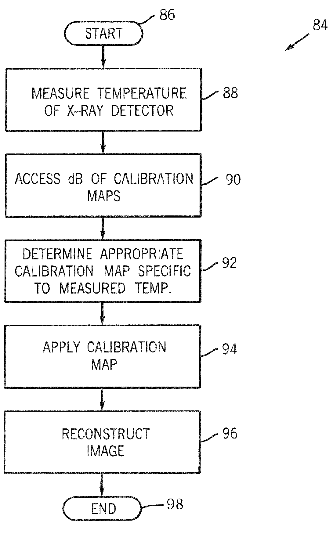
[0016]According to another aspect, the invention is directed to a method of x-ray detector calibration. The method includes determining a temperature of an x-ray detector during data acquisition from a subject to be imaged and selecting a data correction map specific to the temperature of the x-ray detector from a number of stored data correction maps. The selected data correction map is then applied to data acquired by the x-ray detector to reduce artifacts in an image reconstructed from the data acquired by the x-ray detector.
[0020]In accordance with a further aspect, a method of calibrating an offset image for x-ray data correction is provided. The method includes determining a time interval between acquisition of radiographic image data and acquisition of offset image data and determining a magnitude of a power mode transient between the acquisition of radiographic image data and the acquisition of offset image data from the time interval. The method also includes selecting an offset data correction map from a number of offset data correction maps from the magnitude. The selected offset data correction map is designed to reduce a difference between artifacts in the offset image data and the radiographic image data attributable to the power transient.

Problems solved by technology

The chiller, however, adds to the size, weight, and complexity of the detector.
Since natural convection is a passive means of regulating temperature, it can be difficult to timely maintain detector temperature during heavy detector usage periods.
If the intervals between data acquisitions are short, the x-ray detector may not sufficiently cool between data acquisitions to maintain a desired thermal equilibrium.
As a result of the acquisition of data when the detector is outside the desired temperature range, image quality is affected.
Moreover, the calibration and corrective measures generally ignore the specific temperature of x-ray detector even when the temperature is within the desired range.
By failing to take into account the specific temperature of the x-ray detector or that the temperature is outside a predefined temperature range, the calibration and corrective measures may inadequately or improperly applied.
Also affecting the accuracy and precision of x-ray data calibration that is particularly applicable for offset correction is the time interval between the acquisition of x-ray imaging data and the acquisition of offset imaging data.
As a result of the time differences between the acquisition of imaging data and offset data, power transients may introduce artifacts that are not removed in the subtraction process.

Method used


Image

  • Method and system of x-ray data calibration
  • Method and system of x-ray data calibration
  • Method and system of x-ray data calibration

Examples


Embodiment Construction

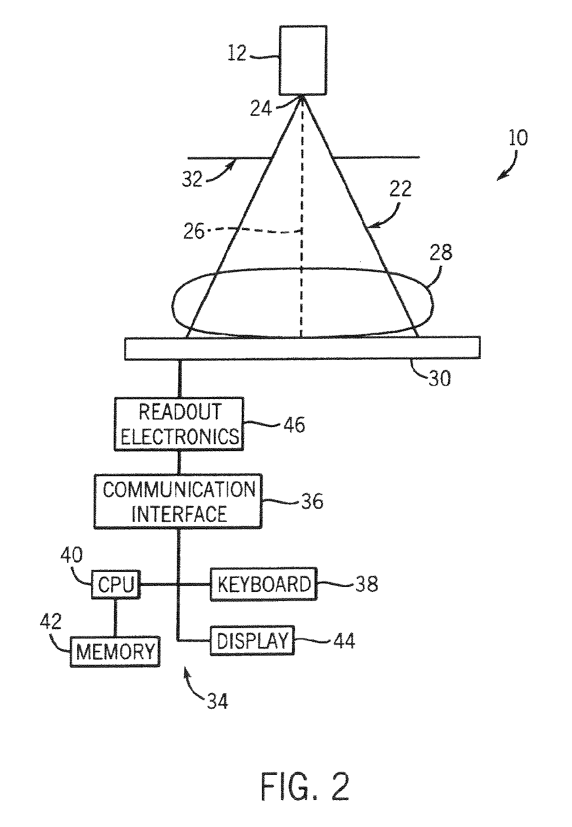
[0037]The present invention will be described with respect to a flat panel, solid-state, indirect detection, and portable digital x-ray detector for use with a mobile x-ray imaging system. However, the present invention is equivalently applicable with other types of x-ray detectors including direct detection digital detectors. Additionally, the present invention may be used with stationary or fixed room x-ray imaging systems. Further, the present application makes reference to an imaging “subject” as well as an imaging “object”. These terms are interchangeable and are not intended to limit the scope of the appending claims.

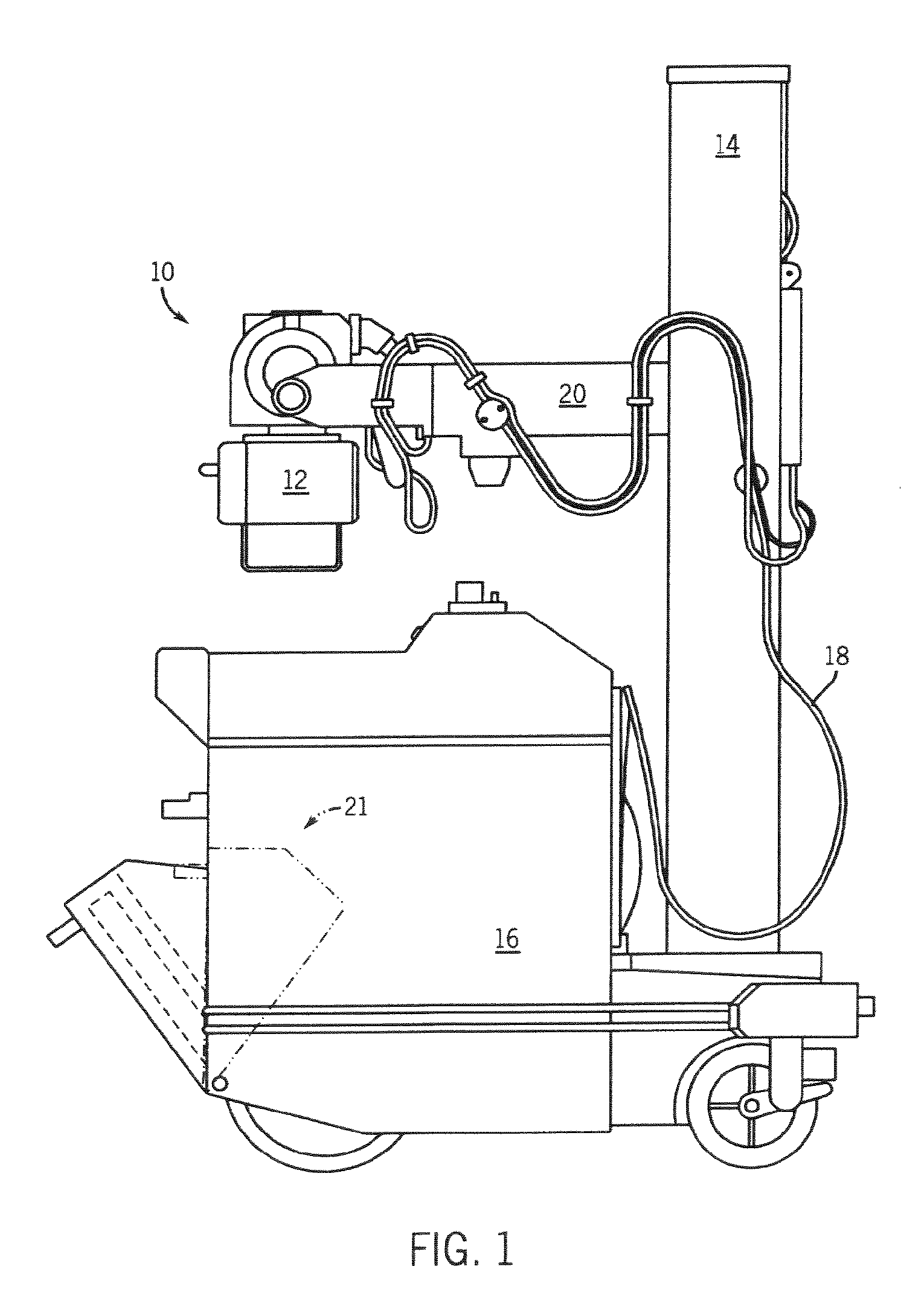
[0038]Referring now to FIG. 1, an exemplary mobile x-ray imaging system 10 applicable with a portable x-ray detector incorporating the present invention is shown. An x-ray source 12 is mounted or otherwise secured to an end of horizontal arm 20. Arm 20 allows the x-ray source 12 to be variably positioned above a subject in such a manner so as to optimize irradiati...


PUM


Abstract

A process of data calibration and correction is disclosed that utilizes feedback from a temperature sensor of an x-ray detector to isolate or otherwise select an appropriate calibration or correction map that is specific to the temperature of the x-ray detector during data acquisition. The method is also designed to take into account changes in power transients of an x-ray detector between the acquisition of imaging data and the acquisition of offset data. The method is particularly applicable in optimally selecting and applying gain correction, conversion factor, bad pixel, and offset calibrations.

Description

CROSS REFERENCE TO RELATED APPLICATION[0001]The present invention is a continuation and claims priority of U.S. patent application Ser. No. 10 / 905,935 filed Jan. 27, 2005.BACKGROUND OF THE INVENTION[0002]The present invention relates generally to diagnostic imaging and, more particularly, to a method and system of calibrating an x-ray detector to reduce artifacts in an image reconstructed from x-ray attenuation imaging data acquired by the x-ray detector.[0003]X-ray imaging is a non-invasive technique to capture images of medical patients for clinical diagnosis as well as inspect the contents of sealed containers, such as luggage, packages, and other parcels. Increasingly, x-ray systems are being used to non-invasively search and / or screen airplane, boat, and train passengers as well as entrants to court buildings, government offices, sporting events, concerts, and other venues of heightened security interest. To capture these images, an x-ray source irradiates a scan subject with a...

Claims


Application Information

Patent Timeline
Patent Type & Authority Applications(United States)
IPC IPC(8): G01D18/00
CPCA61B6/4405A61B6/542A61B6/583A61B6/4291H04N5/3651H04N5/367H04N5/32H04N25/671H04N25/68
Inventor KUMP, KENNETH S.LIU, JAMES Z.
Owner GENERAL ELECTRIC CO
Learn More