
Photoacoustic Assay Method and Apparatus

a technology of photoacoustic assay and apparatus, applied in the field of non-invasive invivo methods and apparatus, can solve the problems of poor spatial resolution of nirs methods and technologies, noise generation of nirs signals, and poor signal-to-noise ratio of nirs methods

Inactive Publication Date: 2008-08-14
GLUCON
View PDF9 Cites 32 Cited by
  • Summary
  • Abstract
  • Description
  • Claims
  • Application Information

AI Technical Summary

Benefits of technology

[0010]An aspect of some embodiments of the present invention relates to providing assay apparatus that uses the photoacoustic effect to assay a target analyte in a spatially localized tissue region and accounts for scattering of light used to generate the photoacoustic effect in determining the assay.

Problems solved by technology

As a result, NIRS methods and technologies generally suffer from poor spatial resolution.
In addition, NIRS signals tend to suffer from noise generated by scattering of light at tissue interfaces, such as the skin, and tissue inhomogeneities.
NIRS methods tend therefore to exhibit relatively poor signal to noise ratios.
NIRS methods and devices, because of their relatively poor spatial resolution generally cannot provide such localized assays.
Accuracy of the assay is generally compromised if contributions to the signals from scattering cross sections of the analytes are not assessed and distinguished from contributions to the signals from absorption cross sections of the analytes.
Prior art has not provided methods for assaying a target analyte in a tissue region responsive to photoacoustic or OCT signals for which scattering cross section contributions to the signals are assessed and distinguished from absorption cross section contributions to the signals.

Method used


Image

  • Photoacoustic Assay Method and Apparatus
  • Photoacoustic Assay Method and Apparatus
  • Photoacoustic Assay Method and Apparatus

Examples


Embodiment Construction

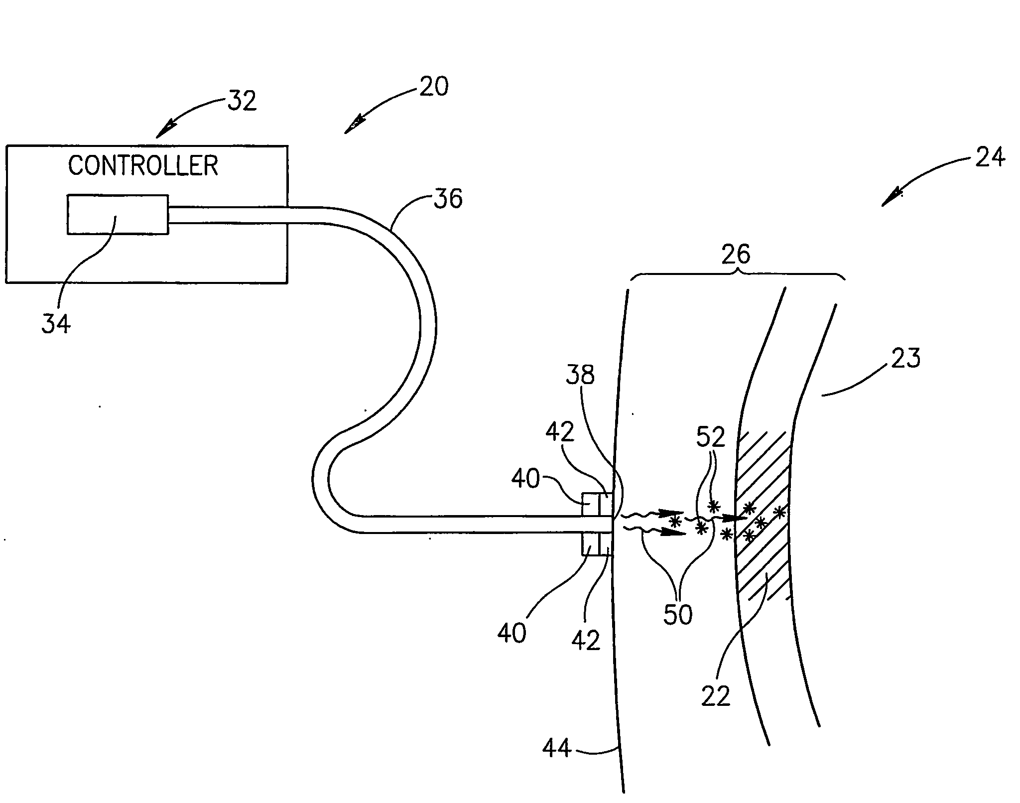
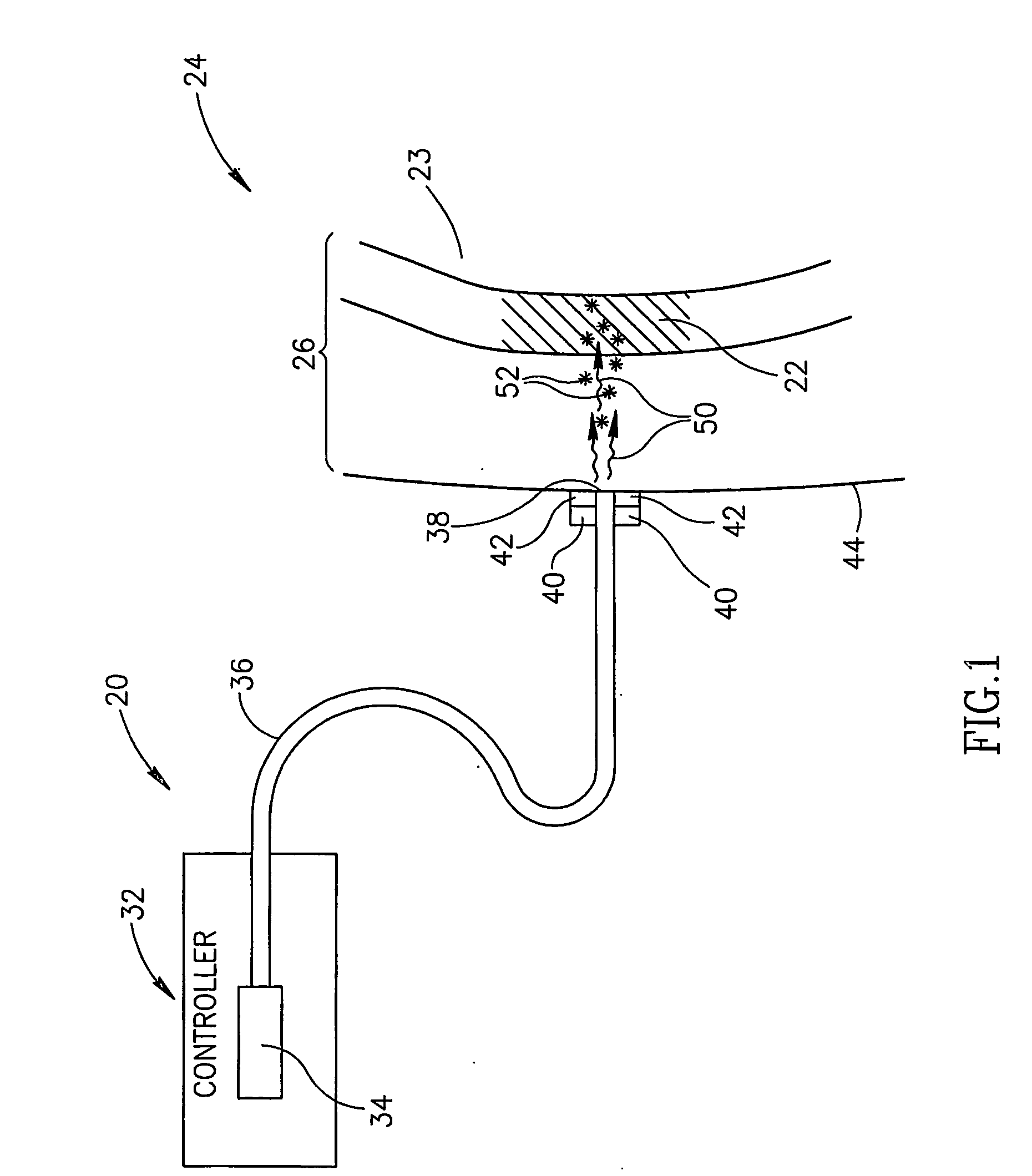
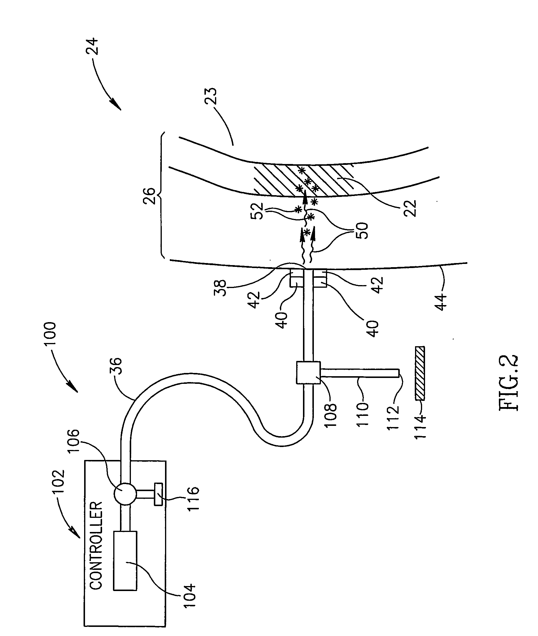
[0049]FIG. 1 schematically shows an assay apparatus 20, hereinafter referred to as a “glucometer”, assaying glucose in a “target region”22 of a body part 24 of a patient, in accordance with an embodiment of the invention. Target region 22 is optionally located in a region 26 of soft tissue of body part 24 and comprises a body fluid, such as for example interstitial fluid, having a concentration of glucose. Optionally, target region 22 is a volume of body fluid having a concentration of glucose and region 26 is a region of a fluid cavity containing the body fluid. For example, as in FIG. 1, target region 22 is a bolus of blood and the fluid cavity a blood vessel 23.

[0050]Glucometer 20 optionally comprises a controller 32, a light source 34, optionally located in the controller, and an optic fiber 36 coupled to the light source. An end 38 of fiber 36 is optionally mounted to a support structure 40, hereinafter a “probe head”, to which an acoustic transducer or array of transducers is ...


PUM


Abstract

Apparatus (20, 100) for assaying a target analyte in a localized tissue region (22) that may include the target and other analytes comprising: a light source (34, 104) that illuminates the region with light at each of a plurality of wavelengths at which light is absorbed and / or scattered by tissue in the region wherein light at a least one of the wavelengths is absorbed or scattered by the target analyte; a signal generator (40) that generates signals responsive to intensity of the light from the light source (34, 104) at different locations in the localized region (22); and a controller (32, 102) that: receives the generated signals; processes the signals to determine an extinction coefficient for light in the localized region at each wavelength; and determines the concentration of the target analyte responsive to a solution of a set of simultaneous equations having as unknown variables concentrations of a plurality of analytes in the region (22), one of which is the target analyte, wherein each equation in the set expresses a relationship between the extinction coefficient, the absorption coefficient and / or the reduced scattering coefficient for light at a different one of the plurality of wavelengths and at least one of the equations expresses a relationship between the extinction coefficient and the reduced scattering coefficient.

Description

FIELD OF THE INVENTION[0001]The invention relates to non-invasive in-vivo methods and apparatus for determining the concentration of a substance in a body.BACKGROUND OF THE INVENTION[0002]Non-invasive methods for assaying a “target” analyte, such as for example glucose, comprised in a region of body tissue are known in the art. In a near infrared spectroscopy (NIRS) method, light at a plurality of different wavelengths in a near infrared band of wavelengths is transmitted into a tissue region of the body to assay a target analyte in the tissue region. Light at least one of the wavelengths, a “target wavelength” is absorbed or scattered by the target analyte. Intensity of light at the different wavelengths that is transmitted through the tissue region or scattered out of the tissue region is measured. The measured intensities are used to isolate and determine the contribution of the target analyte to an absorption or scattering coefficient of the tissue region at the target wavelengt...

Claims


Application Information

Patent Timeline
IPC IPC(8): A61B5/1455A61B8/00A61B5/00G01N21/17
CPCA61B5/0059A61B5/0066A61B5/0095G01N2021/1706A61B5/1455G01N21/1702A61B5/14532
Inventor PESACH, BENNYBITTON, GABRIELBALBERG, MICHAL
Owner GLUCON
Learn More