Concrete Structure Crack Inspection Device and Crack Inspection Method

Inactive Publication Date: 2008-08-14
HARA TOORU
View PDF5 Cites 16 Cited by
  • Summary
  • Abstract
  • Description
  • Claims
  • Application Information

AI Technical Summary

Benefits of technology

[0006]It is an object of the present invention to allow three dimension representation and its strength analysis of the internal structure of the concrete structure which has cracks, to be performed by expressing correctly the positions and shapes of cracks which have been generated on the surface of the concrete structure, with the smaller amount of data.
[0008]Since, in the crack inspection device of the present invention, after binarizing the raster data of the cracks stored in the memory unit, a raster vector conversion processing is carried out thereto, the vector data of the cracks obtained thereby is synthesized and matched with figure data of the surface of the concrete structure, according to coordinates, the positions and shapes of cracks which have been generated in the surface of the concrete structure can be outputted correctly in form of vector data whose amount of data is much smaller than that of raster data.
[0016]In this case, core boring etc. is not necessary and measurement cost becomes low, since the crack depths of a cracks are measured by ultrasonic detection, and since the numeric data of the crack depths is added to the vector data of the cracks corresponding to the positions where the detection is carried out so as to generate three dimension data, the three dimension data can be quantified more in accuracy, compared with the case where the numeric data of the crack depths is added to the cracks by worker's sketches.

Problems solved by technology

However, in the crack inspection method depending on such sketches, there are no criteria for checking the sketches to the actual crack, and the length and the pattern of the cracks is influenced by the subjectivity of the worker who sketches them, and further thin cracks may be overlooked, or the cracks having a complicated pattern may not be drawn, so that it is very inaccurate.
However, since in the conventional inspection method of the cracks, the image processing is performed by using the raster data obtained with the digital image pick-up machine, without any change, the cracks can be grasped with markedly sufficient accuracy when counting the number of pixels or totaling the brightness values of the respective pixels, in comparing with the sketches by a manpower, and since the amount of data for expressing one crack, however, becomes huge, and information of the position, shape and the like lacks in the raster data itself, there are drawbacks that the internal structure of the concrete structure which has cracks cannot be expressed in three dimension, the concrete structure cannot be used for the strength calculation in an FEM analysis, or neither crack length nor crack volume can be calculated automatically.

Method used


Image

  • Concrete Structure Crack Inspection Device and Crack Inspection Method
  • Concrete Structure Crack Inspection Device and Crack Inspection Method
  • Concrete Structure Crack Inspection Device and Crack Inspection Method

Examples


Embodiment Construction

[0025]Hereafter, embodiments of the present invention will be explained, based on drawings.

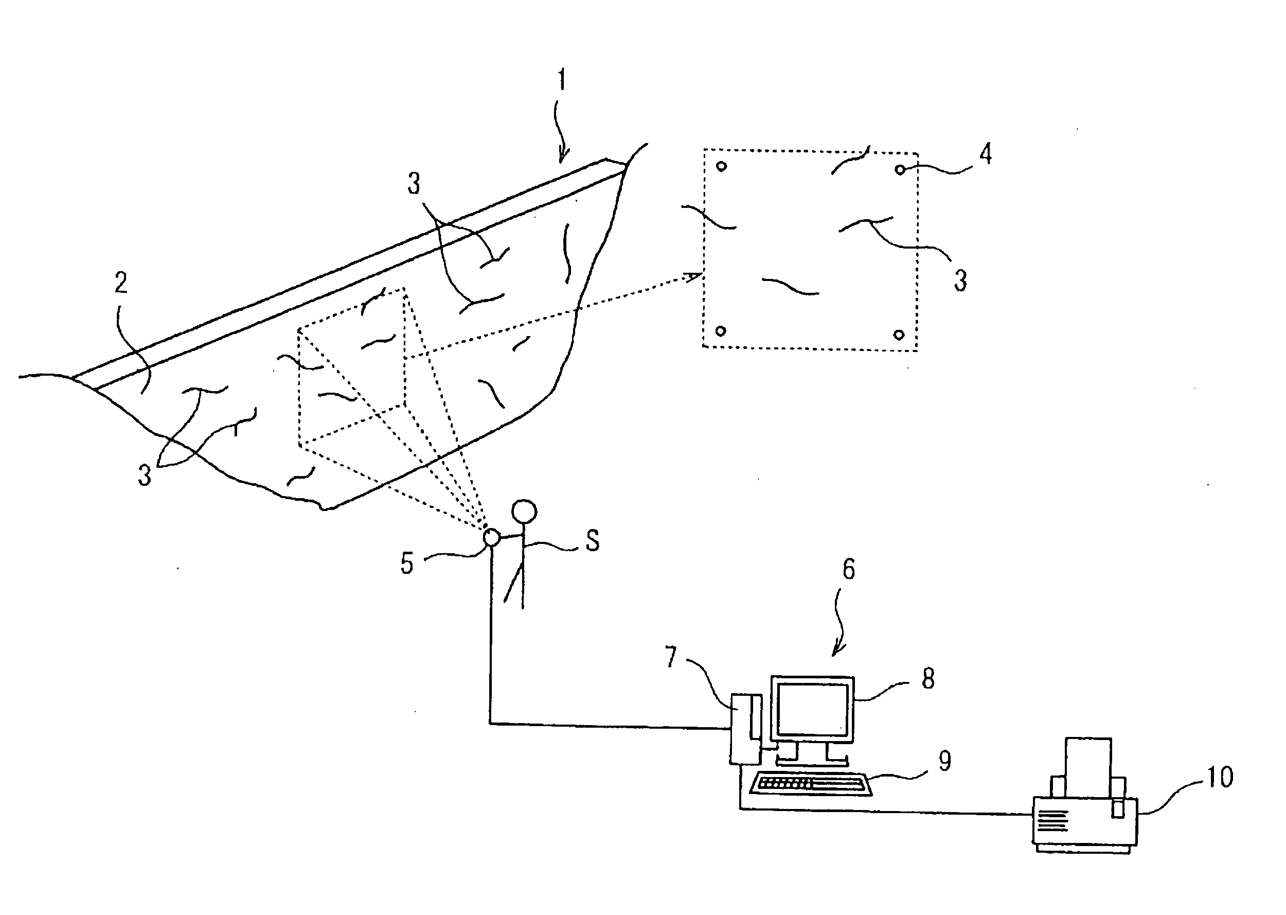
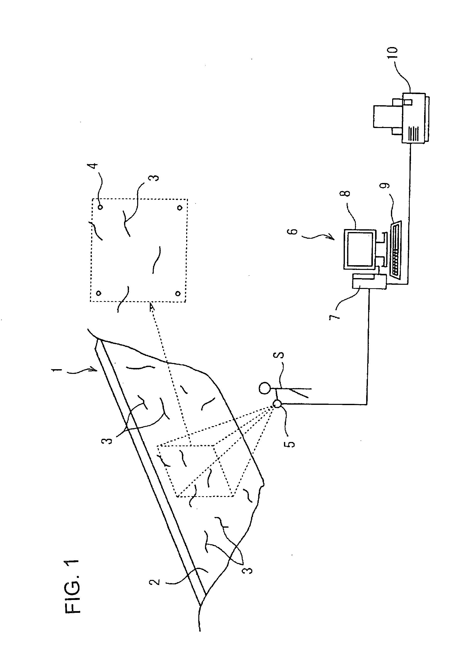
[0026]FIG. 1 is a schematic view of an example of a crack inspection device of the concrete structure according to the present invention. As shown in this figure, in this embodiment, a dam is selected as a concrete structure 1 which is the subject of examination of cracks, and many cracks 3 have occurred in a surface 2 of this dam 1. This dam 1 has a comparatively large-sized concrete structure in which upside cracks 3 cannot be reached, unless a scaffold is built, and the width thereof is about twenty meters, and the maximum height of the central portion is about 10 meters.

[0027]Reference points 4 are beforehand marked on four corners of an exact rectangle area whose image should be taken, by a laser pointer (not shown) on the surface 2 of the dam 1. As shown as a broken line area in FIG. 1, a worker S who takes an image at the spot determines an image pick-up range so that these reference po...


PUM


Abstract

A crack inspection device (6) for a concrete structure (1) includes: storage means for storing raster data obtained by imaging a surface (2) of the concrete structure (1) having a crack (3); conversion means for performing raster vector conversion on the data obtained by digitizing the raster data; data superimposing means for superimposing the vector data of the crack (3) obtained by the conversion means on the graphic data of the surface (2) of the concrete structure (1) while matching the coordinates; and output means for outputting the superimposed data obtained by the data superimposing means.

Description

TECHNICAL FIELD[0001]The present invention relates to a crack inspection device and a crack inspection method of a concrete structure, capable of grasping correctly the actual condition of cracks generated on the surface of the concrete structure, and the proof stress of the concrete structure without destroying it.BACKGROUND ART[0002]When the state of cracks generated on the surface of a comparatively large-sized concrete structure which has a height of several meters, for example, the concrete structure such as a revetment built on a slope of a mountain, a dam and the like, is inspected, usually, a worker checks the cracks with eyes and makes sketches in handwriting. However, in the crack inspection method depending on such sketches, there are no criteria for checking the sketches to the actual crack, and the length and the pattern of the cracks is influenced by the subjectivity of the worker who sketches them, and further thin cracks may be overlooked, or the cracks having a comp...

Claims


Application Information

Patent Timeline
IPC IPC(8): G01N21/88G01B11/30
CPCG01N21/8851G01N29/043G01N29/0609G06T7/0004G01N33/383G01N2291/02854G01N29/0618
Inventor HARA, TOORUKOBORI, KENICHI
Owner HARA TOORU
Why Eureka
Try Eureka