Modular Column System Using Internally Confined Hollow Column Unit and Method of Constructing the Same

a column system and column unit technology, applied in the field of modules, can solve the problems of long construction period, large expense, and pier problems, and achieve the effect of convenient assembly of the units

Inactive Publication Date: 2008-08-21
HANBAT NAT UNIV IND ACADEMIC COOPERATION FOUND
View PDF7 Cites 33 Cited by
  • Summary
  • Abstract
  • Description
  • Claims
  • Application Information

AI Technical Summary

Benefits of technology

[0027]Accordingly, the present invention has been made keeping in mind the above problems occurring in the related art, and an object of the present invention is to provide a modular column system using at least one internally confined hollow column unit, in which the internally confined hollow column unit includes an outer pipe section formed of steel or fiber reinforced plastic (FRP), a concrete section filled with concrete and forming a hollow section inside the outer pipe section, and an inner pipe section installed in the hollow section of the concrete section and formed of steel or FRP, which confines the concrete section, thereby providing easy assembly of the units as well as economical construction due to the advantages derived from construction using a general modular column system, due to the hollow section, and due to a reduction in self-weight caused by reduction of a cross section, and improving corrosion resistance by means of the inner and outer pipe sections formed of FRP in the case of, for example, an underwater pier.

Problems solved by technology

For this reason, a long construction period and great expense are required for the work of setting up the formwork and dismantling the formwork after curing the concrete.
Further, problems with the pier can occur depending on the construction location.
For example, in the case of constructing an elevated roadway, the pier creates a traffic jam around the construction site.
Further, in the situation where the work environment is unfavorable, as in underwater work, the construction and management of the pier are difficult, and the possibility of faulty construction is increased.
However, when constructing this pier, it is difficult to set up the formwork for fabricating units having convex and concave shapes.
Practically, due to its self-weight, the precast unit made of concrete has nothing but to be lifted by a crane, so that, when constructing a high pier, the number of precast units to be fabricated is excessively increased.
However, the solid cross-section reinforced concrete pier has various disadvantages in that it is difficult to apply to a place where the foundation section encounters a structural problem due to the self-weight thereof, that it is economically unfavorable due to the increase in concrete material cost, and in that it encounters a chance of cracks occurring due to the generation of the heat of hydration when concrete is poured.
However, the steel pier generally has a relatively greater width over the thickness of a deck constituting the pier, and thus has a problem in that it is vulnerable to local buckling when earthquakes occur.
However, CFT has a problem in that the material expense thereof is very high.
Further, CFT still has a problem in that, when constructed as a high pier, it is increased in cross section and self-weight and thus is unsuitable for on-site conditions having restrictions on the ratio of width to thickness.
In addition, CFT encounters a problem of maintenance for preventing corrosion thereof in on-site conditions, in which the corrosion becomes an issue, as in the underwater pier.
Further, in the case in which the pier of the bridge or the column of a building has a structural problem due to the excessive self-weight of concrete, or the material expense of the concrete is relatively high, a pier or a column having a hollow cross section is used, instead of one having a solid cross section.
Especially, as earthquake-proof design is currently becoming a hot issue, there is a necessity to design a pier or column capable of withstanding a greater bending moment, and furthermore, transverse displacement is required.
However, the ductile capacity of the hollow cross-section pier or column is doubtful, because it is difficult to expect a concrete confining effect therefrom.
In other words, due to brittle fracture behavior caused in the inside of the hollow cross section because there is no concrete confining effect, the pier or column having a hollow cross-section evidences poor ductile capability in practice.
Nevertheless, in the case of modular piers proposed to date, no special study has been made of excessive self-weight in the case of using concrete for the precast unit, high material expense in the case of using CFT as a material for replacing concrete, whether to introduce the hollow cross section as an approach to resolve the increase in cross section and self-weight when constructing a high pier, the brittle fracture of the hollow cross section in the case of using the hollow cross section, and maintenance in the case of using CFT for, for example, an underwater pier.

Method used


Image

  • Modular Column System Using Internally Confined Hollow Column Unit and Method of Constructing the Same
  • Modular Column System Using Internally Confined Hollow Column Unit and Method of Constructing the Same
  • Modular Column System Using Internally Confined Hollow Column Unit and Method of Constructing the Same

Examples


Embodiment Construction

[0043]Reference will now be made in greater detail to an exemplary embodiment of the invention, an example of which is illustrated in the accompanying drawings. Wherever possible, the same reference numerals will be used throughout the drawings and the description to refer to the same or like parts.

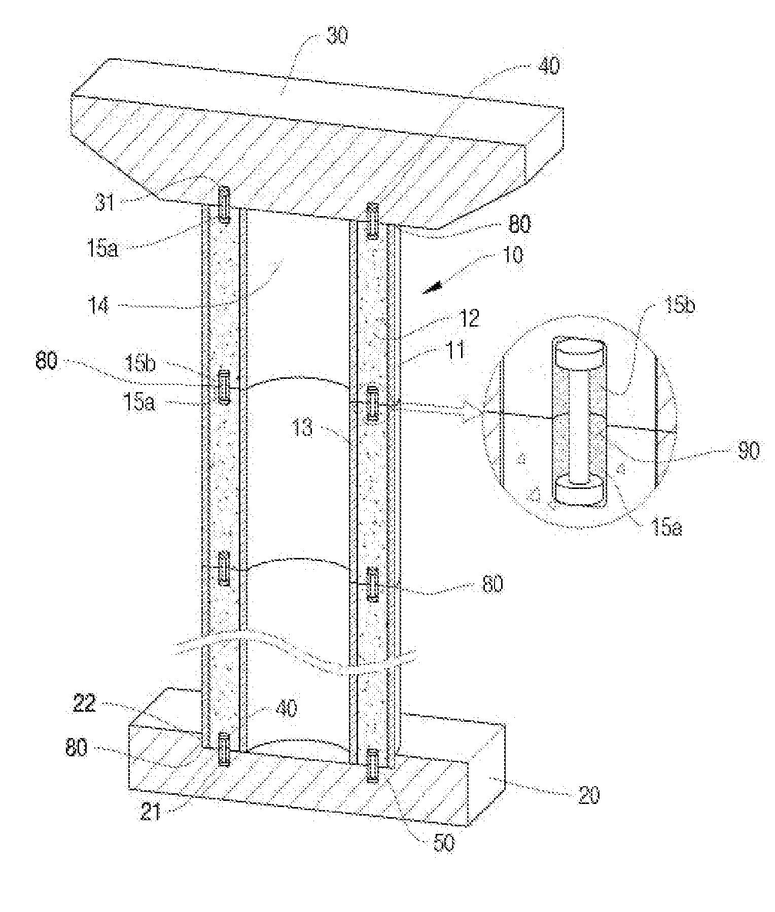
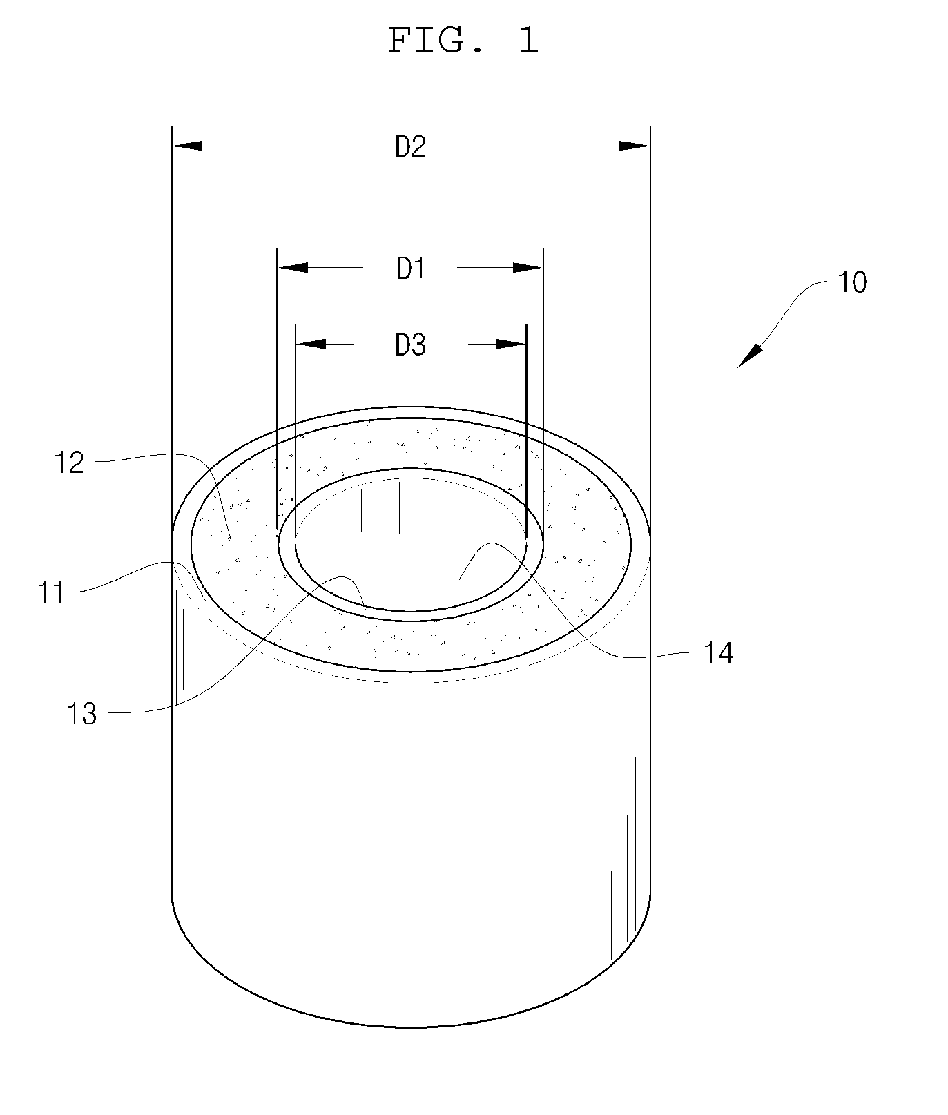
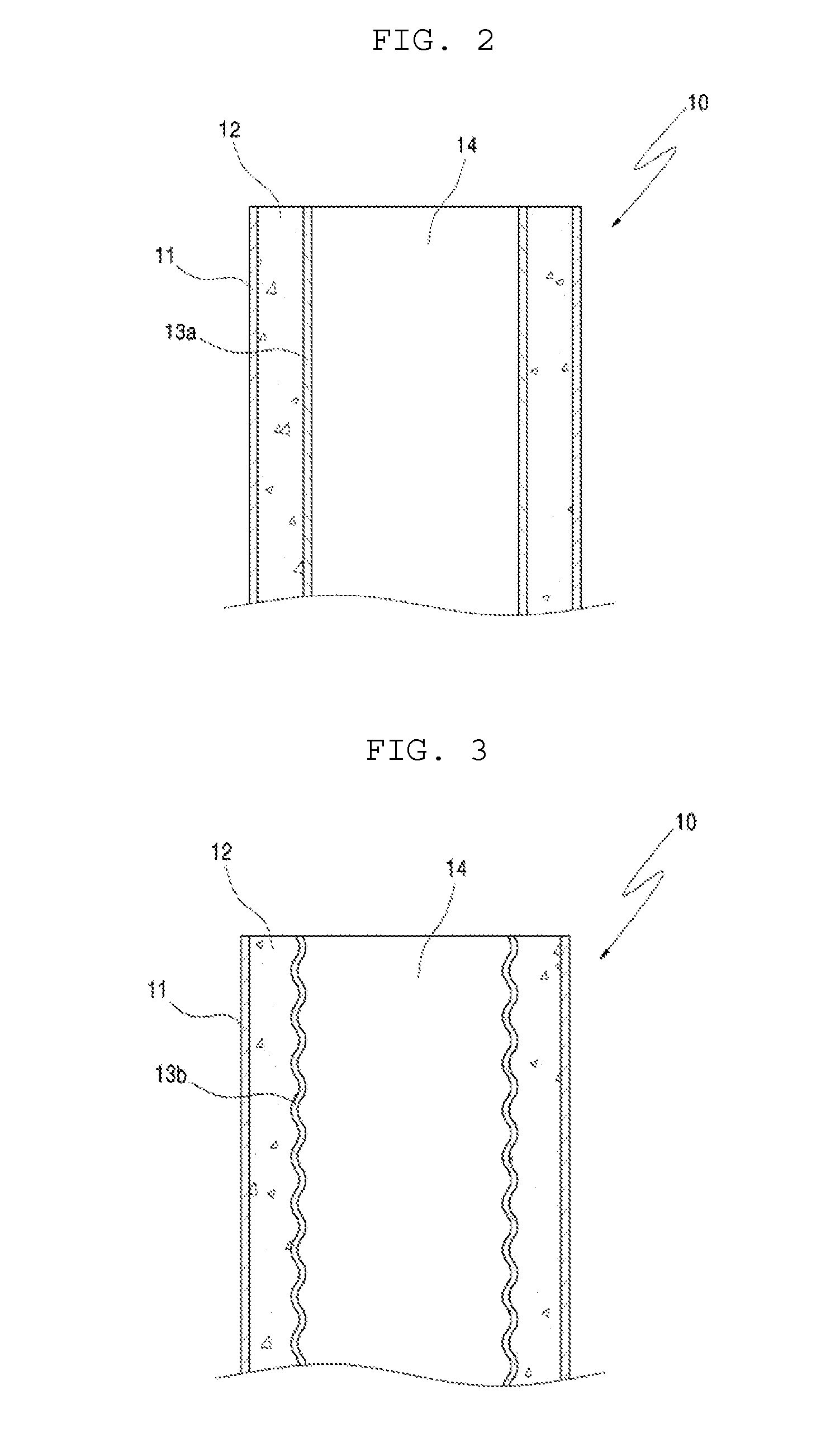
[0044]As illustrated in FIG. 1, an inner pipe section 13 is installed in the hollow section 14 of a concrete section 12, and thus it confines the concrete section 12. Thus, the concrete section 12 is under a triaxial compression load. Thereby, when a precast unit is fabricated, the hollow section 14 of the concrete section 12 is formed so as to reduce the self-weight of the precast unit to facilitate assembly, thereby preventing incidental brittle fracture in the cross section of the hollow section 14 of the concrete section 12. Further, the inner pipe section 13 is inserted to reinforce the resistance to bending moment as well as to reduce the cross section and self-weight of the precast...


PUM

PropertyMeasurementUnit
shapeaaaaaaaaaa
resistanceaaaaaaaaaa
self-weightaaaaaaaaaa

Abstract

A modular column system and a method of constructing the same are constructed by stacking at least one precast unit between a foundation section and a coping section. The precast unit makes use of an internally confined hollow column unit fabricated in advance, and joint sections between the precast units are firmly formed. Thereby, the modular column system can realize a short construction period and economy because reinforcement bars and forms are not used, as well as high resistance to bending moment and reduction in cross section and self-weight of the precast unit, and thus the modular column system can provide easier and more economical assembly, and prevent brittle fracture of the joint section between the precast units.

Description

BACKGROUND OF THE INVENTION[0001]1. Field of the Invention[0002]The present invention relates, in general, to a modular column system constructed by stacking at least one precast unit between a foundation section and a coping section, as well as a method of constructing the same, in which the precast unit makes use of an internally confined hollow column unit fabricated in advance, and in which a joint section between the precast units is firmly formed. As a result, the modular column system realizes a short construction period and economy because reinforcement bars and forms are not used, and also realizes high resistance to bending moment and a reduction in cross section and self-weight of the precast unit, so that the modular column system enables easier and more economical assembly, and prevents brittle fracture of the joint section between the precast units.[0003]2. Description of the Related Art[0004]Generally, piers constructed in bridge work are cast-in-place concrete struct...

Claims


Application Information

Patent Timeline
Patent Type & Authority Applications(United States)
IPC IPC(8): E02D27/00E04B1/00
CPCE01D19/02E01D2101/24E04C3/34E01D2101/40E01D2101/268
Inventor KANG, YOUNG JONGHAN, TAEK HEEHAN, SANG YUN
Owner HANBAT NAT UNIV IND ACADEMIC COOPERATION FOUND
Why Eureka
Try Eureka