
Base Unit for Dual Wiring System

a dual-wired, base unit technology, applied in the direction of electrical apparatus casings/cabinets/drawers, coupling device connections, instruments, etc., can solve the problems of not easy to perform repair work, not easy for general users to add a new function to the multimedia receptacle panel, and difficulty in repairing work, so as to improve the degree of layout freedom, facilitate exchangeability, and improve the effect of function expansion

Inactive Publication Date: 2008-08-21
MATSUSHITA ELECTRIC WORKS LTD
View PDF22 Cites 17 Cited by
  • Summary
  • Abstract
  • Description
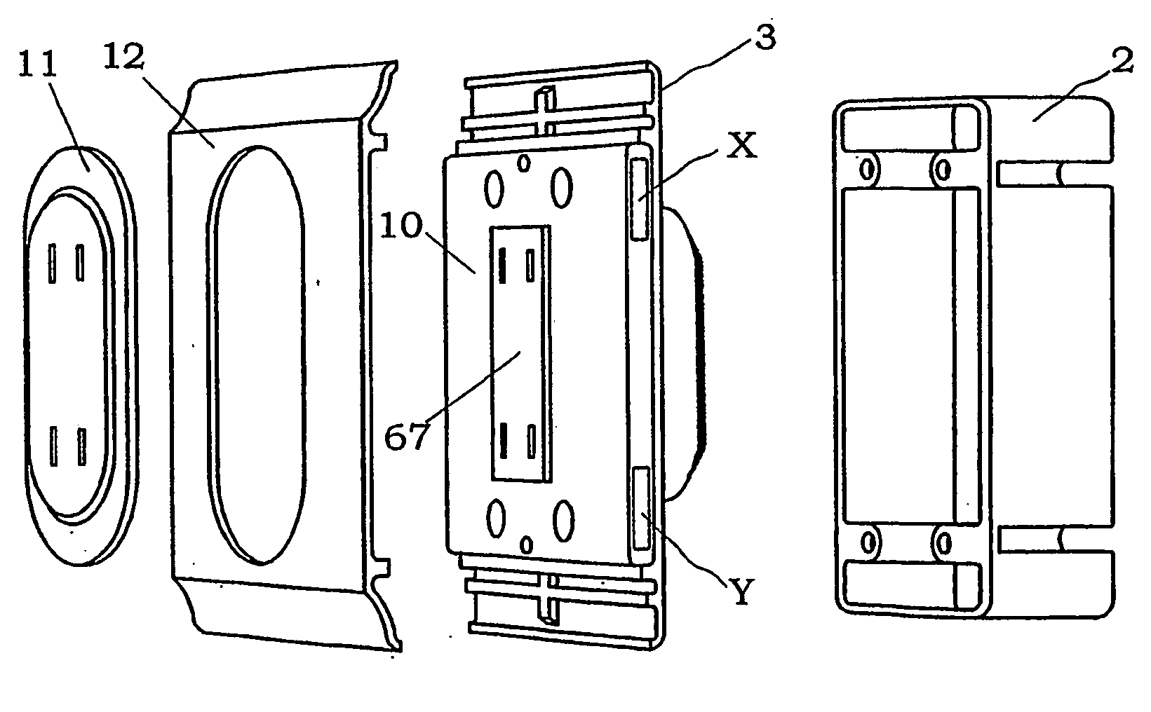
  • Claims
  • Application Information

AI Technical Summary

Benefits of technology

[0005]Therefore, a primary concern of the present invention is to provide a base unit suitable for a dual wiring system with improved function expandability and easy exchangeability.
[0006]That is, the base unit for the dual wiring system of the present invention is adapted in use to be mounted in a wall surface of a structure, and connected to both of an electric power line and an information line installed in the structure. The base unit is characterized by having one of a module connector and a module port, which is detachably connected to the other one of the module connector and the module port formed in a function unit to simultaneously establish both of supplying the electric power from the base unit to the function unit, and making a signal transmission between the base unit and the function unit, thereby enabling the function unit to provide at least one of functions for supplying an electric power from the electric power line, outputting information from the information line, and inputting information into the information line.
[0007]According to the present invention, since both of the supply of electric power from the base unit to the function unit and the mutual communication of the information signal between the base unit and the function unit can be simultaneously obtained by the connection between the module connector and the module port, a general user can easily exchange the function unit already connected to the base unit for another function unit without performing a laborious repair work. In addition, when a plurality of base units are mounted in wall surfaces at plural locations in the structure, each of the base units are sharable among a plurality of function units having various kinds of functions such as receptacle, switch, sensor, controller, monitor and speaker. Therefore, an increased degree of freedom of layout of the function units provides comfortable and convenient living and working environments to meet the user's needs.
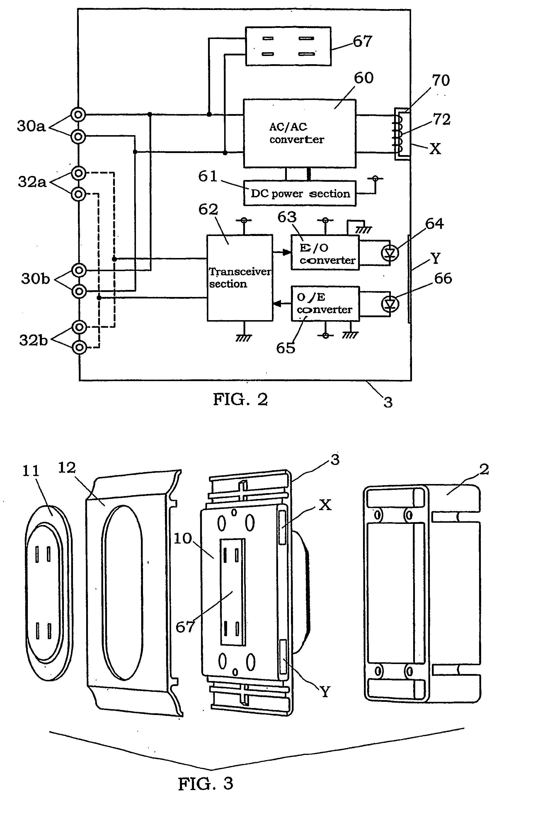
[0008]In the above base unit for the dual wiring system, it is preferred that the module connector and the module port have a pair of an electric power connector and an electric power port, which are detachably connected to each other to supply the electric power from the base unit to the function unit, and a pair of an information signal connector and an information signal port, which are detachably connected to each other to make the signal transmission between the base unit and the function unit. In particular, it is preferred that the electric power port and the electric power connector are configured to supply the electric power from the base unit to the function unit by means of electromagnetic coupling, and the information signal port and the information signal connector are configured to make the signal transmission between the base unit and the function unit by means of optical coupling. In this case, since the electric power transmission and the signal transmission between the base unit and the function unit are performed in a noncontact manner by means of the electromagnetic and optical couplings, it is possible to minimize transmission loss of the electric power and / or the electric signal therebetween, and operate the function unit with reliability.
[0009]In addition, it is preferred that the base unit has a housing, which is formed with a rear portion having terminals to be connected to the electric power line and the information line, front portion having at least one of an outlet configured to receive a power plug of an electric appliance, and a switch configured to turn on / off the electric appliance, and a side portion having the one of the module connector and the module port such that the function unit is detachably connected to the base unit in a direction along the wall surface. In this case, it is possible to improve function expandability in the dual wiring system without spoiling the beauty in the interior spaces. Alternatively, the base unit may have a housing, which is formed with a rear portion having terminals to be connected to the electric power line and the information line, and a front portion having the one of the module connector and the module port.
[0010]Moreover, it is preferred that the base unit of the present invention further includes a joining means configured to mechanically connect the function unit to the base unit. For example, the joining means is formed with an engaging portion such as elongated projection and groove formed on the base unit, and a joining member configured to slidably contact the engaging portion and make the mechanical connection between the base unit and the function unit when a region of the joining member is engaged to the engaging portion of the base unit and the remaining region of the joining member is engaged to an engaging portion formed on the function unit. In this case, it is possible to improve the reliability of the supply of electric power and the mutual communication of the information signal between the base unit and the function unit, and prevent an accidental falling of the function unit from the base unit.

Problems solved by technology

Therefore, after the construction works are finished, it is difficult to add a new function to the multimedia receptacle panel or exchange a part of the functions of the existing multimedia receptacle panel for another function.
In addition, when exchanging the existing multimedia receptacle panel for another multimedia panel, a repair work is needed.
However, such a repair work is not easy for general users to perform, and the costs of the repair work become a burden to the user.

Method used


Image

  • Base Unit for Dual Wiring System
  • Base Unit for Dual Wiring System
  • Base Unit for Dual Wiring System

Examples


Embodiment Construction

[0026]A base unit for dual wiring system of the present invention is explained in detail according to the following preferred embodiments.

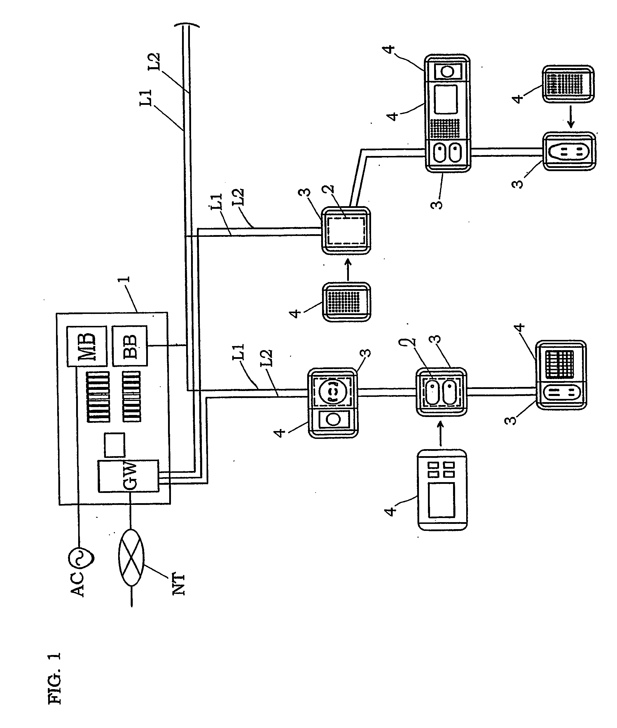
[0027]As shown in FIG. 1, the dual wiring system of this embodiment has a power supply line L1 and an information line L2 installed in a building structure, which are connected to commercial power source AC and the internet network NT through a distribution board 1, switch boxes 2 embedded in wall surfaces at plural locations in the building structure, base units 3 mounted in the switch boxes and connected to the power supply line L1 and the information line L2, and a plurality of function units 4 each having the capability of providing at least one of functions for supplying electric power from the electric power line L1, outputting information from the information line L2 and inputting information into the information line L2 when connected with one of the base units 3. In the present specification, the wall is not limited to the sidewall formed...


PUM


Abstract

A base unit suitable to improve easy exchangeability of a function unit in a dual wiring system is provided. The base unit is mounted in a wall surface of a structure, and connected to both of an electric power line and an information line previously installed in the structure. The base unit has a module port, which is detachably connected to a module connector of the function unit to simultaneously establish both of supplying the electric power from the base unit to the function unit, and making a signal transmission between the base unit and the function unit, thereby enabling the function unit to provide at least one of functions for supplying electric power from the electric power line, outputting information from the information line and inputting information into the information line when connected with the base unit.

Description

TECHNICAL FIELD[0001]The present invention relates to a dual wiring system, which can be used for the supply of electric power and the input and output of information through an electric power line and a signal line installed in a structure.BACKGROUND ART[0002]Due to popularization of the Internet, it has been demanded to ensure the accessibility to information networks at many locations in building structures such as general houses and office buildings. For example, Japanese Patent Early Publication [kokai] No. 11-187154 discloses a multimedia g system having a distribution board for controlling an electric power line and various kinds of signal lines installed in a structure in a centralized control manner, and a multimedia receptacle panel, which is adapted in use to be mounted in an indoor wall surface, and connected to the distribution panel through the electric power line and the signal lines. For example, the multimedia receptacle panel has a power receptacle for supplying co...

Claims


Application Information

Patent Timeline
IPC IPC(8): H05K5/00H02G3/02H02J17/00H04Q9/00
CPCH01R25/006H01R25/164Y04S20/228Y02B70/325H04L12/2803H01R25/00H02G3/00H04L12/40Y02B70/30Y04S20/20
Inventor YAMAMOTO, MASAHIROUENO, TAKESHIOOGI, KAZUFUMIYONEYAMA, KENICHIHAMAGUCHI, HIDESHI
Owner MATSUSHITA ELECTRIC WORKS LTD
Learn More