Rollover protection system for motor vehicles with a sensor-controlled actively deployable rollover body

a technology of active deployment and protection system, which is applied in the directions of vehicle safety arrangements, pedestrian/occupant safety arrangements, transportation and packaging, etc., can solve the problems of component and assembly costs and cost as well

Inactive Publication Date: 2008-08-21
AUTOMOTIVE GROUP ISE INNOMOTIVE SYST EURO
View PDF10 Cites 7 Cited by
  • Summary
  • Abstract
  • Description
  • Claims
  • Application Information

AI Technical Summary

Benefits of technology

[0017]Therefore in the inventive locking device, the locking action occurs directly on the rollover body, in particular in the case of a U-shaped roll bar on its two bar arms. Because of the length of the pawl arrangement extending across the width of the rollover body and because of the spaced simultaneous engagement of the extensions (which can also be described as arm extensions) with the rollover body, in particular with its bar arms, the locking device is stressed relatively evenly by the centrally impacting rollover forces. In addition, only one pawl arrangement is required for the locking action, which reduces the component and assembly expense—and thus the cost—as well. In addition, in the case of a U-shaped roll bar, the traverse with the latch arbor can be dispensed with. The holder of the roll bar affixed to the vehicle, the so-called massively designed guide block, can also be designed much more simply, since its only task now is to guide the bar arms. Thus it would be conceivable to construct the guide block using simple tubes with welded-on flanges.
[0023]Meanwhile, if the force conveyed to the inner bar arm is greater than to the outer bar arm, in principle corresponding stops on the arm tubes can prevent the more weakly stressed arm tube from being pushed upward due to leverage.
[0026]In the case of supports at different heights, the single rotary detent pawl comes to rest against the rollover body in a diagonal position when the deployed protective position is attained. A rotary detent pawl arranged in such a way is intended to come more and more into a horizontal position with increasing load, so that a strengthening effect results with respect to the achievable locking force. In the case of U-shaped roll bars, for example, depending on the design of the supports in the bar arm tubes, either a greater jamming of the rotary detent pawl between the bar arm tubes or an enlarged bearing or supporting surface on the front face under the free ends of the bar arm tubes will be the result.
[0028]Because of the pre-tensing retaining spring, the ends of the extensions of the detent pawl arrangement butt against the corresponding guides on the rollover body, e.g. against the inner surfaces of the arm tubes in the case of a U-shaped roll bar, with a certain frictional force. In this way, it is advantageous in the case of a pyrotechnic drive system that no separate holding mechanism is required to hold down the rollover body. The ends of the arm tubes rest in a foam cushion at the base, in order to avoid clattering or vibrational noises while driving. To increase the holding force, the system can also be held with positive locking.

Problems solved by technology

In addition, only one pawl arrangement is required for the locking action, which reduces the component and assembly expense—and thus the cost—as well.

Method used


Image

  • Rollover protection system for motor vehicles with a sensor-controlled actively deployable rollover body
  • Rollover protection system for motor vehicles with a sensor-controlled actively deployable rollover body
  • Rollover protection system for motor vehicles with a sensor-controlled actively deployable rollover body

Examples


Embodiment Construction

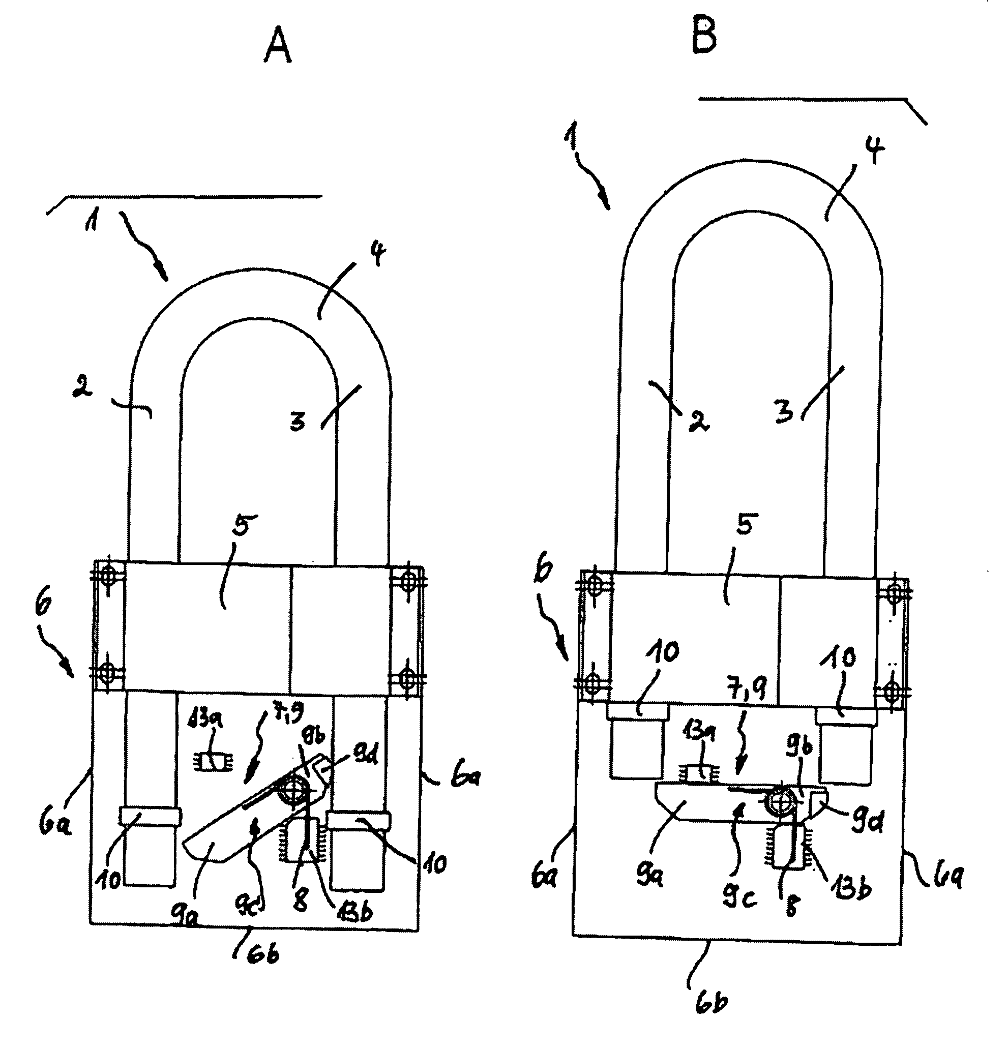
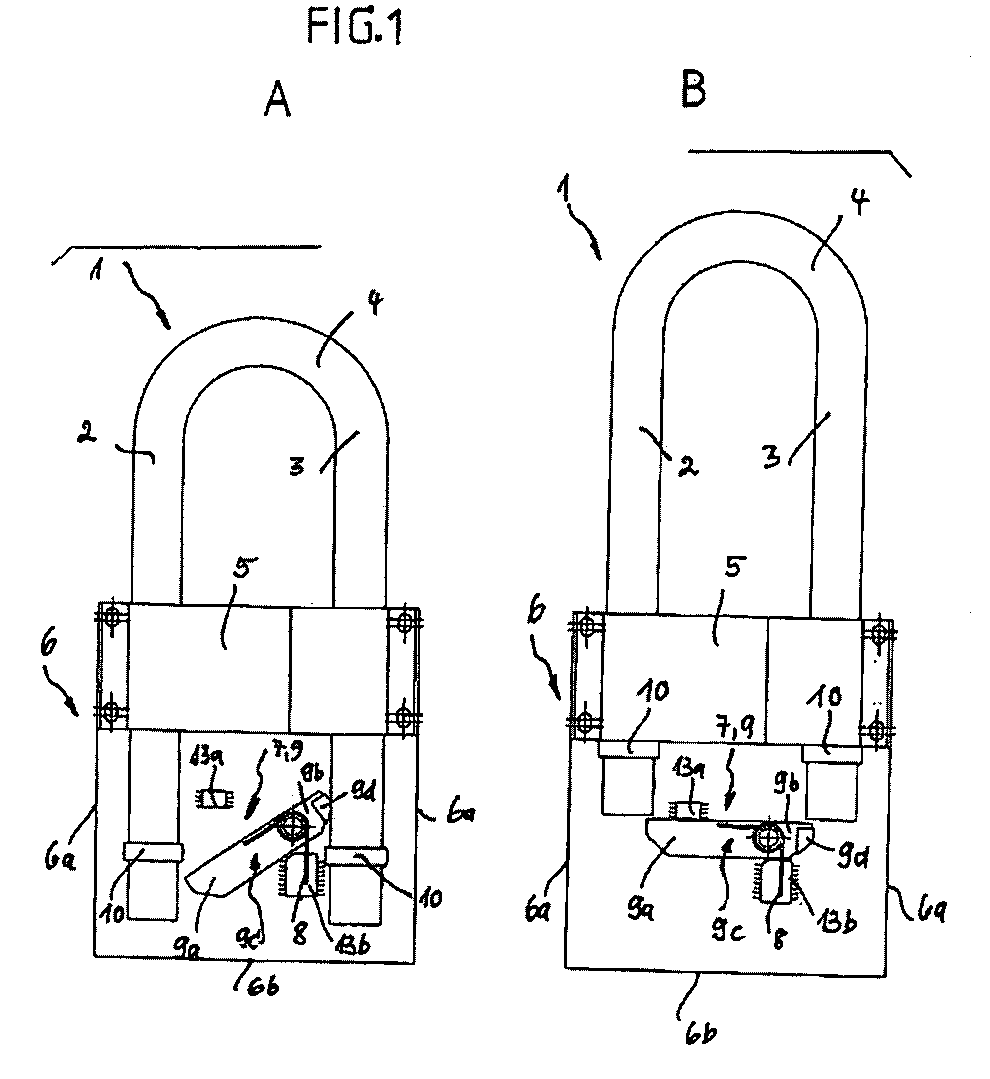
[0035]FIG. 1, in its two parts A, B, shows schematic front views of an initial variant of an active rollover protection system for motor vehicles furnished with the inventive locking device. This system has a U-shaped roll bar 1 as the rollover body, which has two tube shaped bar arms or arm tubes 2,3 that are connected to one another by means of a cross yoke in the form of a rounded bar head 4. The bar arms or arm tubes 2, 3 are held and guided in a holder 5 affixed to the vehicle, the so-called guide block, which is part of a cassette-like guide housing 6 with side parts 6a and a base part 6b.

[0036]Such rollover protection systems are known in a wide variety of embodiments, e.g. from DE 100 40 649 C2 cited at the start, and therefore do not need to be described in detail here. Nor is it necessary to describe the drive for sensor-controlled deployment of the roll bar from a resting position (Figure Part A) into a protective position (Figure Part B), whereby the drive can typically...


PUM


Abstract

The invention is based on a known rollover protection system for motor vehicles with a rollover body that is held guided in a holder affixed to the vehicle, a drive under spring tension for sensor-controlled deployment of the rollover body from a resting position to a protective position, and a locking device for the rollover body when deployed in the protective position. In order to create a very simple, low-cost and yet highly effective locking device, i.e. a block against retraction of the roll bar after a deployment due to an accident, the invention provides a detent pawl arrangement articulated in a pivoting manner and affixed to the vehicle and under spring tension in the locking direction by a retaining spring, with two extensions extending at least across the width of the rollover body, that in the protective position of the rollover body can be pivoted into direct active contact with corresponding supports on the rollover body.

Description

BACKGROUND OF THE INVENTION[0001]1. Field of the Invention[0002]The invention relates to a rollover system for motor vehicles with a rollover body held guided in a holder affixed to the vehicle, a drive for sensor-controlled deployment of the rollover body from a resting position to a protection position, and a locking device for the rollover body deployed in a protective position.[0003]2. Description of Related Art[0004]Such rollover protection systems are for protecting passengers in motor vehicles without a protective roof, typically in convertibles or roadsters, so that the vehicle rolls over the deployed rollover body, which creates a survival area for the passengers in a rollover.[0005]It is known to provide a roll bar that extends the entire width of the motor vehicle and is designed as part of the body. In this solution, the increased air resistance and vehicle noise generated is perceived as disadvantageous, apart from the impairment of the vehicle's appearance.[0006]It is ...

Claims


Application Information

Patent Timeline
Patent Type & Authority Applications(United States)
IPC IPC(8): B60R21/13
CPCB60R2021/135B60R21/13
Inventor LATUSSEK, HOLGER
Owner AUTOMOTIVE GROUP ISE INNOMOTIVE SYST EURO
Why Eureka
Try Eureka