
Block noise detector and detection method, and block noise reducer and reduction method

a block noise detector and detection method technology, applied in the field of video signal processing, can solve the problems of significant luminance, block noise (also called block distortion), and failure to detect edges, so as to reduce the circuit size of the block noise detector, reduce the circuit size of the block noise reducer, and detect more accurately

Inactive Publication Date: 2008-08-21
MITSUBISHI ELECTRIC CORP
View PDF5 Cites 8 Cited by
  • Summary
  • Abstract
  • Description
  • Claims
  • Application Information

AI Technical Summary

Benefits of technology

[0008]An object of the present invention is to reduce the circuit size of a block noise detector and a block noise reducer.
[0009]Another object of the invention is to improve the accuracy of a block noise detector by detecting block boundaries even when large signal variations occur on one side of the boundary.
[0016]The counters are reset each time their contents are output in synchronization with the horizontal synchronizing signal. Accordingly, comparatively small counters suffice, reducing the circuit size of the block noise detector.
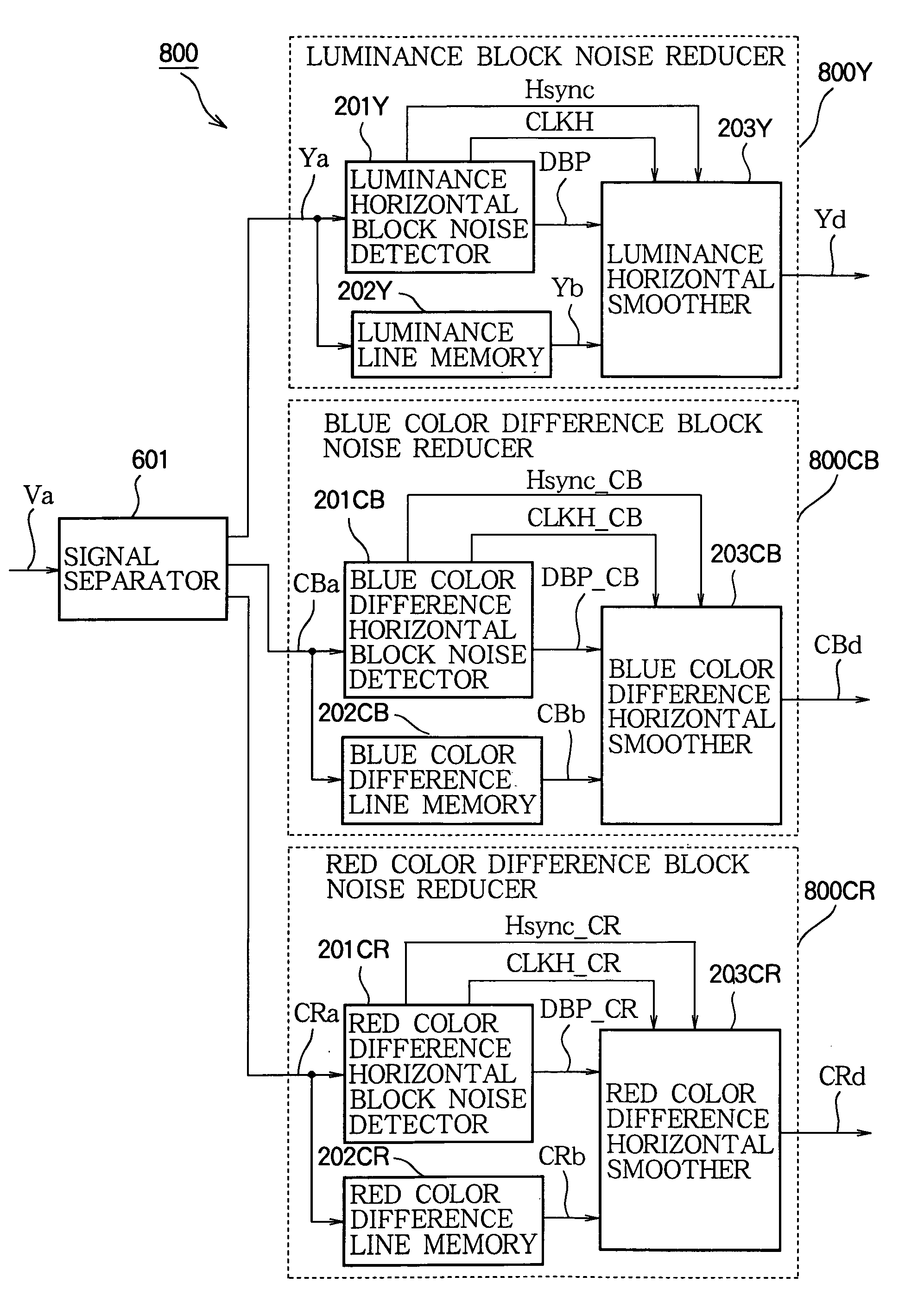
[0017]A block noise reducer incorporating this block noise detector only has to store one horizontal line of the input video signal, instead of an entire field or frame, so the circuit size of the block noise reducer is further reduced.
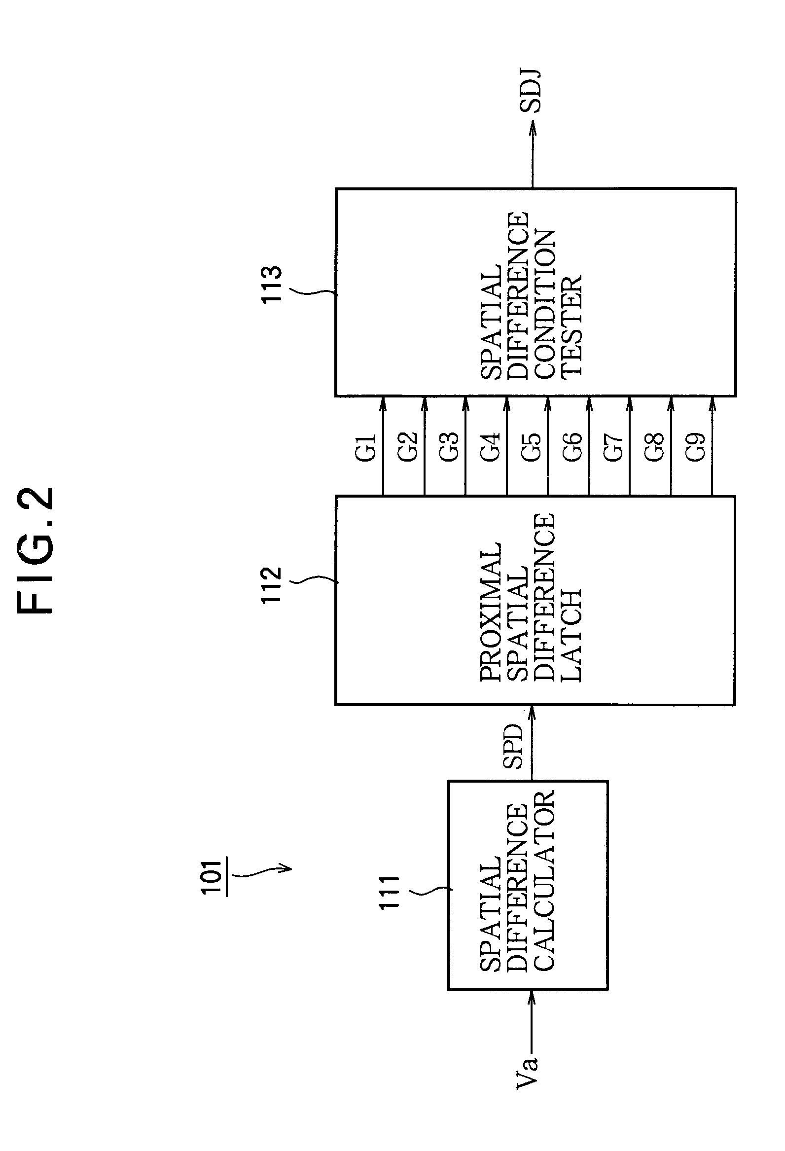
[0018]In edge detection at a position corresponding to a spatial difference are detected, the spatial difference comparator may compare the spatial difference separately with neighboring spatial differences to the left and neighboring spatial differences to the right, and an edge may be detected if a predetermined condition is satisfied with respect to either the neighboring spatial differences to the left or the neighboring spatial differences to the right. Edges can then be detected even at points at which the input video signal varies significantly on one side of the edge. Block boundaries can accordingly be detected more accurately then by the conventional averaging scheme.

Problems solved by technology

Block noise (also called block distortion) occurs when processing discontinuities at the block boundaries make the blocks visible in the decompressed video picture.
One problem with this known block noise detector is that it can fail to detect edges at which there is significant luminance variation one side of the edge but not on the other side.
Another problem is that large counters are needed to count edges over an entire video field or frame, and wide data paths are needed to process the resulting counts, making the block noise detector circuit large in size.
A related problem is that a large memory is needed to store the video signal for one field or frame awaiting block noise detection, since noise reduction cannot begin until the block boundaries have been detected.
A block noise reducer employing this block noise detector therefore has a very large circuit size.

Method used


Image

  • Block noise detector and detection method, and block noise reducer and reduction method
  • Block noise detector and detection method, and block noise reducer and reduction method
  • Block noise detector and detection method, and block noise reducer and reduction method

Examples


first embodiment

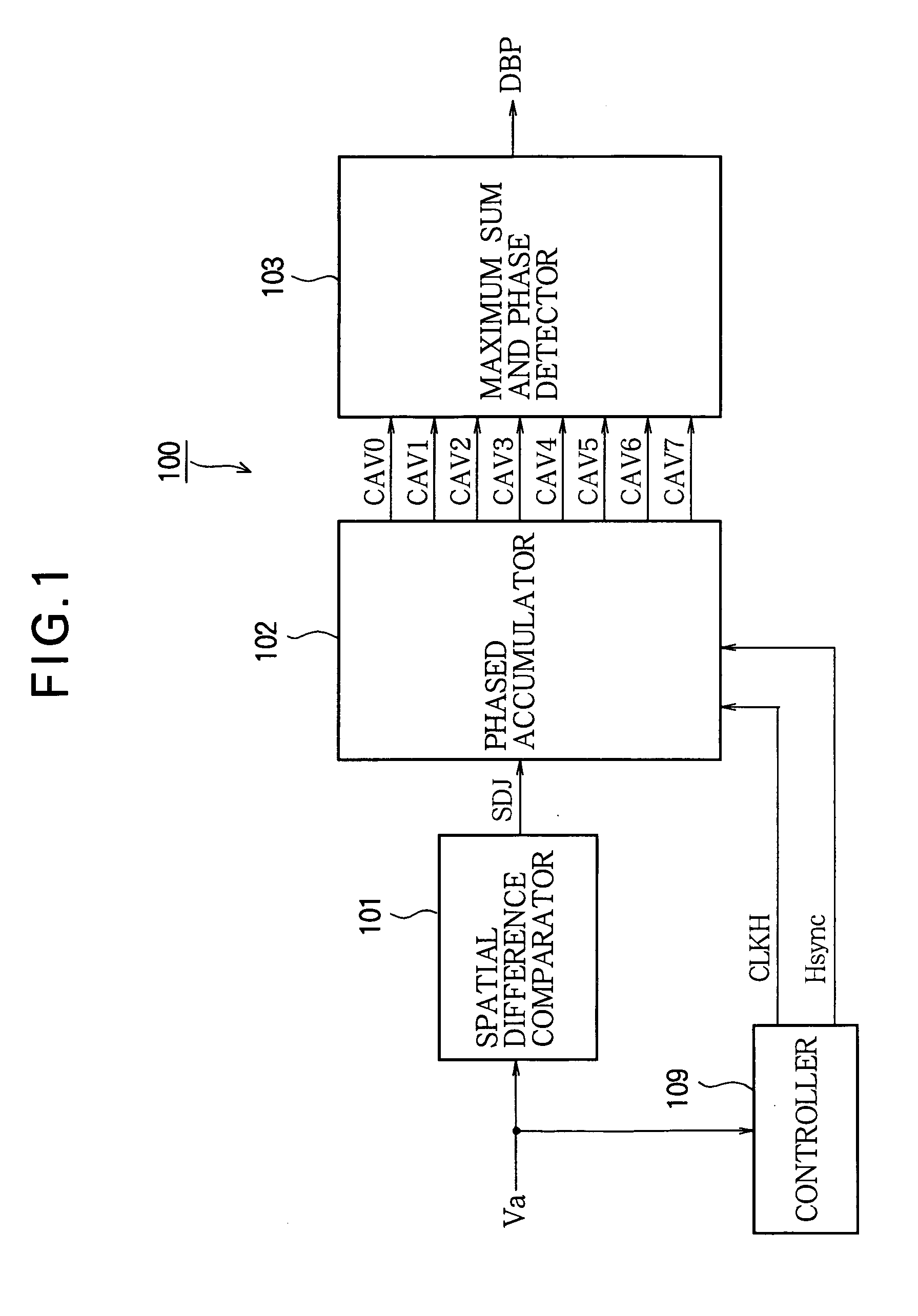
[0042]Referring to FIG. 1, the block noise detector 100 in the first embodiment comprises a spatial difference comparator 101, a phased accumulator 102, a maximum sum and phase detector 103, and a controller 109.

[0043]A monochrome input video signal Va is supplied to the spatial difference comparator 101 and the controller 109. The controller 109 extracts a horizontal synchronizing signal Hsync from the input video signal Va, generates a pixel clock signal CLKH with a period equal to the pixel sampling period, synchronized to the horizontal synchronizing signal Hysnc, and supplies CLKH and Hsync to the phased accumulator 102.

[0044]The controller 109 also extracts a vertical synchronizing signal Vsync, which is used together with the horizontal synchronizing signal to control the spatial difference comparator 101 and maximum sum and phase detector 103. A detailed description of the vertical synchronization operations will be omitted.

[0045]The spatial difference comparator 101 calcula...

second embodiment

[0084]Referring to FIG. 12, the block noise detector 300 in the second embodiment differs from the block noise detector 100 in FIG. 1 in the first embodiment by adding a phase consistency tester 104 on the output side of the maximum sum and phase detector 103. The maximum sum and phase detector 103 supplies the maximum phase signal MAP to the phase consistency tester 104.

[0085]The controller 109 in the block noise detector 300 in FIG. 12 extracts the horizontal synchronizing signal Hsync and vertical synchronizing signal Vsync from the input video signal Va, and supplies Hsync and Vsync to the phase consistency tester 104.

[0086]The phase consistency tester 104 stores the maximum phase signal MAP for eight consecutive lines, compares the eight stored values, and outputs the maximum phase signal MAP as the detected block phase signal DBP if the eight MAP values are identical.

[0087]An example of the internal structure of the phase consistency tester 104 is shown in FIG. 13. The phase c...

third embodiment

[0100]Referring to FIG. 16, the block noise detector 500 in the third embodiment differs from the block noise detector 100 in FIG. 1 in the first embodiment by adding a thresholder 105 on the output side of the maximum sum and phase detector 103. The maximum sum and phase detector 103 supplies the maximum value signal MAS and the maximum phase signal MAP to the thresholder 105.

[0101]The thresholder 105 compares the input maximum value signal MAS with a threshold value and outputs the maximum phase signal MAP as the detected block phase signal DBP, but outputs the detected block phase signal DBP only when the maximum value signal MAS is greater than the threshold value.

[0102]Because the block noise detector 500 outputs the detected block phase signal DBP only when the maximum value signal MAS is greater than the threshold value, as described above, the block noise detector 500 does not mistakenly detect a rectangle forming part of the image in a video field as block noise.

[0103]A blo...


PUM


Abstract

A block noise detector has a spatial difference calculator that calculates differences between values of adjacent pixels. A spatial difference comparator detects edges by comparing the calculated differences. Eight counters count edges detected at different groups of positions spaced eight pixels apart in each horizontal line. The maximum count and the group of positions at which it occurs are detected at the end of each horizontal line to detect block noise and the positions of the block boundaries. The block noise detector is small in size because it only has to count edges in one line at a time, and detects edges accurately by comparing the difference at a given position separately with differences to the left and differences to the right.

Description

BACKGROUND OF THE INVENTION[0001]1. Field of the Invention[0002]The present invention relates to video signal processing, more particularly to the detection and reduction of the block noise that often occurs when a digital video signal is transmitted or recorded in a compressed form.[0003]2. Description of the Related Art[0004]Commonly used video data compression algorithms operate on 8×8 blocks of picture elements (pixels). Block noise (also called block distortion) occurs when processing discontinuities at the block boundaries make the blocks visible in the decompressed video picture. Detecting block noise and reducing it by appropriate filtering is a known art.[0005]One known block noise detector, disclosed in PCT Patent Application Publication No. WO2005-004489, employs an edge detector, an edge counter, and a boundary identifier. The edge detector recognizes an edge when the luminance change at a point exceeds the average luminance change at nearby points to the right and left,...

Claims


Application Information

Patent Timeline
IPC IPC(8): G06K9/40
CPCH04N19/117H04N19/14H04N19/86H04N19/182H04N19/80H04N19/186
Inventor NAMIKI, RYOSUKENAGASE, AKIHIROYOSHII, HIDEKIKAGAWA, SHUICHISOMEYA, JUNSUGIURA, HIROAKI
Owner MITSUBISHI ELECTRIC CORP
Learn More