Embossing Roller, Embossing Device Including Said Roller and Paper Article Produced With Said Embossing Device

a technology of embossing roller and embossing pattern, which is applied in the field of devices for embossing web materials, can solve the problems of incompatibility of embossing pattern and embossing pattern with correct operation, and the embossing pattern cannot accept any type of embossing pattern

Inactive Publication Date: 2008-08-21
FABIO PERINI SPA
View PDF12 Cites 29 Cited by
  • Summary
  • Abstract
  • Description
  • Claims
  • Application Information

AI Technical Summary

Benefits of technology

[0016]Moreover, in the various embodiments colored glues can be used to combine an embossing effect with a chromatic decorative effect.
[0017]The particular arrangement of the embossed or printed patterns according to the invention makes it possible to obtain a plurality of technical-functional and aesthetic effects of considerable emphasis. In fact, the secondary embossed patterns arra...

Problems solved by technology

However, embossing is also used to define limited areas, at the level of which a glue is applied to join together two or more plies forming the finished multi-ply product.
The technical and aesthetic functions have different requirements, which are often incompatible.
This poses serious limits to the type of decoration obtainable with embossing.
Moreover, embossing machines or embossing units cannot accept any type of embossing pattern, as this has considerable effects on dynamic stresses.
The embossing pattern, in particular the distribution and dimension of the protuberances, has a considerable influence on dynamic phenomena in machines, ...

Method used


Image

  • Embossing Roller, Embossing Device Including Said Roller and Paper Article Produced With Said Embossing Device
  • Embossing Roller, Embossing Device Including Said Roller and Paper Article Produced With Said Embossing Device
  • Embossing Roller, Embossing Device Including Said Roller and Paper Article Produced With Said Embossing Device

Examples


Embodiment Construction

[0047]The description below refers specifically to embossing rollers and patterns, but as mentioned above, at least some of the advantages attained by the invention are also useful in the printing field, especially to print multi-ply tissue paper products.

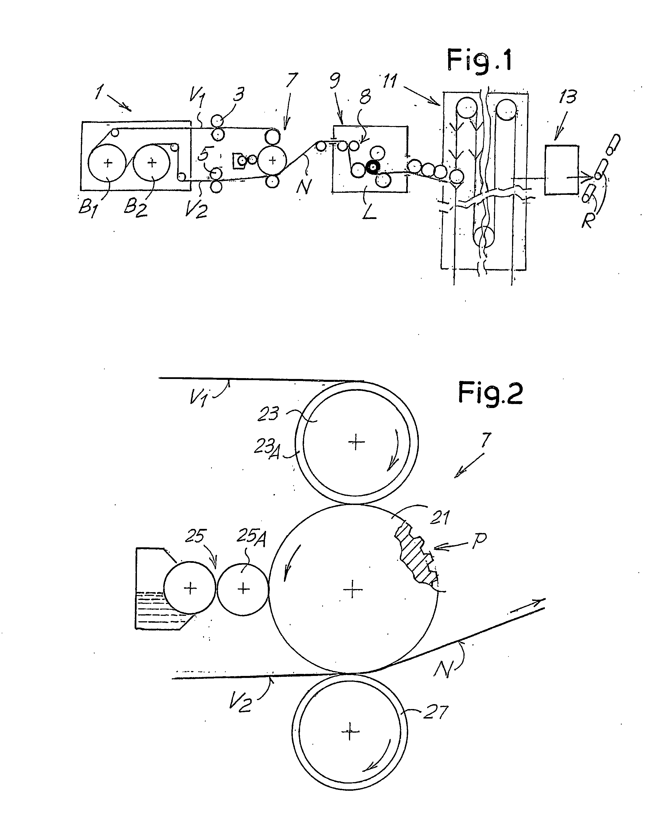
[0048]FIG. 1 schematically shows a portion of a line for converting tissue paper and producing rolls of toilet paper or kitchen towels. The line comprises an unwinder 1, in which two reels B1 and B2 of large diameter are unwound to feed the line. The plies fed from the reels B1 and B2 are indicated with V1 and V2.

[0049]Arranged along the feed path of the plies V1 and V2 are respective auxiliary embossing units 3 and 5, each of which can, for example, have a steel embossing roller and a pressure roller cooperating therewith. The auxiliary embossing units 3 and 5 can be designed conventionally and provided to impress background embossing on the two plies V1 and V2, for example micro-embossing composed of a fine geometrical pattern fo...


PUM

PropertyMeasurementUnit
Fractionaaaaaaaaaa
Fractionaaaaaaaaaa
Angleaaaaaaaaaa

Abstract

The embossed or printed web material article comprises at least two plies (V1, V2) of tissue paper joined together by gluing and forming at least one multi-ply sheet. The sheet has a principal pattern (D), embossed or printed, in a substantially intermediate position with respect to the surface of the article, and secondary embossed or printed patterns (U, V) of smaller dimensions arranged along the edge lines of the article and interrupted by said edge lines. FIG. 3 schematically shows an axonometric view of the embossing roller (21). The cylindrical surface of which is indicated with 21S. Defined on the surface of the roller are annular i.e. circumferential areas or bands (21C), along which protuberances are arranged to define an embossing pattern, which will be referred to hereunder as circumferential secondary embossing pattern. A longitudinal band (21L) is also represented on the cylindrical surface of the embossing roller. In actual fact, several longitude bands are provided along the circular extension of the roller. As in case of the circumferential bands, protuberances defining an embossing pattern, which will be referred to hereinafter a longitude secondary embossing pattern, are also provided along the longitudinal bands.

Description

TECHNICAL FIELD [0001]The present invention relates to innovations to devices for embossing web materials, and especially webs or sheets of paper, in particular tissue paper, to produce rolls of toilet paper, kitchen towels, paper napkins or similar products.[0002]More specifically, the invention relates to improvements concerning the configuration of the embossing rollers and of the embossed product.STATE OF THE ART [0003]In the production of rolls of tissue paper, or crepe or absorbent paper to form rolls of toilet paper, kitchen towels and the like, one or more plies of paper are usually subjected to an embossing operation, with which the paper material is permanently deformed to form thereon protuberances of various shapes. Embossing, which also causes localized breakage of the cellulose fibers forming the paper web, has a technical-function object, consisting in increasing the softness and volume of the finished product, together with its absorption capacity. However, embossing...

Claims


Application Information

Patent Timeline
IPC IPC(8): B32B3/28B31F1/07B32B37/12B32B37/00B32B29/00
CPCB31F1/07B31F2201/0733B31F2201/0761B31F2201/0794Y10T428/24934Y10T156/15Y10T428/15Y10T156/1304Y10T428/24612
Inventor GELLI, MAURO
Owner FABIO PERINI SPA
Why Eureka
Try Eureka