Method And Apparatus For Cooling A Material To Be Removed From The Grate Of A Fluidized Bed Furnace

a fluidized bed furnace and material cooling technology, which is applied in the field of methods and apparatuses, can solve the problems of inability to accurately adjust the temperature as desired, the mass flow of the material to be removed from the fluidized bed furnace and cooled cannot be controlled and accurately regulated, and the mass flow of the material cannot be accurately controlled and controlled. , to achieve the effect of accurate control of the charge, easy automation, and increase or decrease the amount of material

Inactive Publication Date: 2008-08-21
OUTOTEC OYJ
View PDF11 Cites 36 Cited by
  • Summary
  • Abstract
  • Description
  • Claims
  • Application Information

AI Technical Summary

Benefits of technology

[0018]The method and apparatus of the invention prevent excessive flow of material out of the fluidized bed furnace, but they make it possible to get the coarse fraction out in a charge-by-charge manner so that the quantity of the charge is accurately controlled. Due to the accurately controlled output flow from the fluidized bed furnace and the cooling controlled on the basis of its temperature, the mass flow and quantity of the material to be passed out of the fluidized bed furnace and cooled as well as the final temperature after cooling can be controllably adjusted. Therefore, the counter-pressure of the bed in the fluidized bed furnace and the composition of the bed can be controllably regulated by making desired adjustments of the quantity of material contained in the material charge to be cooled. The apparatus can be easily automated. The method and apparatus allow the operator to know how much material is removed from the furnace, because the charge size is controlled and the number of charges (charges per hour) can be adjusted. This makes it easy to increase or decrease the amount of material to be removed from the furnace by changing the times, in other words, if its preferable in respect of furnace operation to remove more material by underflow, then the operation is accelerated, or if it is desirable to reduce the amount of material removed by underflow, then the operation is slowed down. The system enables controlled removal by underflow of a quantity of material that is suitable in respect of furnace operation. The quantity of material removed is known and the quantity can be adjusted. This is part of the control of the furnace. In addition, the temperature is under control and the composition of the material removed can be monitored by a sampling system. The essential point is that the invention enables an adjustable system to be achieved.
[0019]In an embodiment of the method, during the loading step a), the surface level of the material accumulating in the fluidized bed cooler is measured, and when the measured surface level has reached a predetermined limit value, which corresponds to a predetermined quantity of a charge to be loaded at one time, the supply of material into the fluidized bed cooler is prevented.
[0020]In an embodiment of the method, during the loading step a), the fluidization air counter-pressure caused by the material is measured, and when the measured counter-pressure has reached a predetermined limit value, which corresponds to a predetermined quantity of a charge to be loaded at one time, the supply of material into the fluidized bed cooler is prevented.

Problems solved by technology

A problem with the prior-art apparatus and method is that the mass flow of the material to be removed from the fluidized bed furnace and cooled can not be controllably and accurately regulated.
A further problem is that, in cooling occurring in a continuous flow, the material temperature after the cooling may vary within wide limits and the temperature can not be accurately adjusted as desired.
A problem with this prior-art apparatus and method is that the mass flow of the material to be removed from the fluidized bed furnace and cooled and the quantity of the charge can not be accurately measured.

Method used


Image

  • Method And Apparatus For Cooling A Material To Be Removed From The Grate Of A Fluidized Bed Furnace
  • Method And Apparatus For Cooling A Material To Be Removed From The Grate Of A Fluidized Bed Furnace

Examples


Embodiment Construction

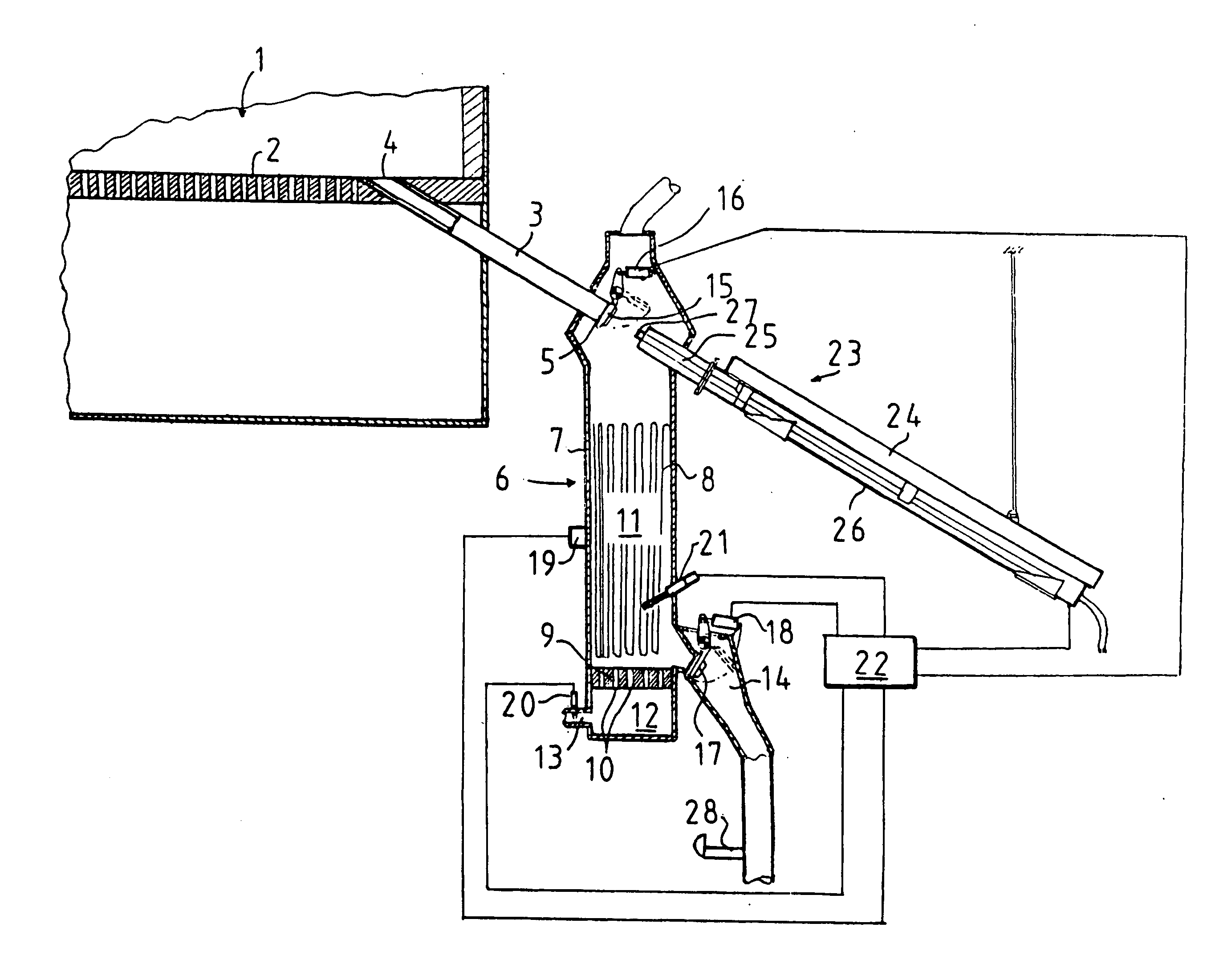
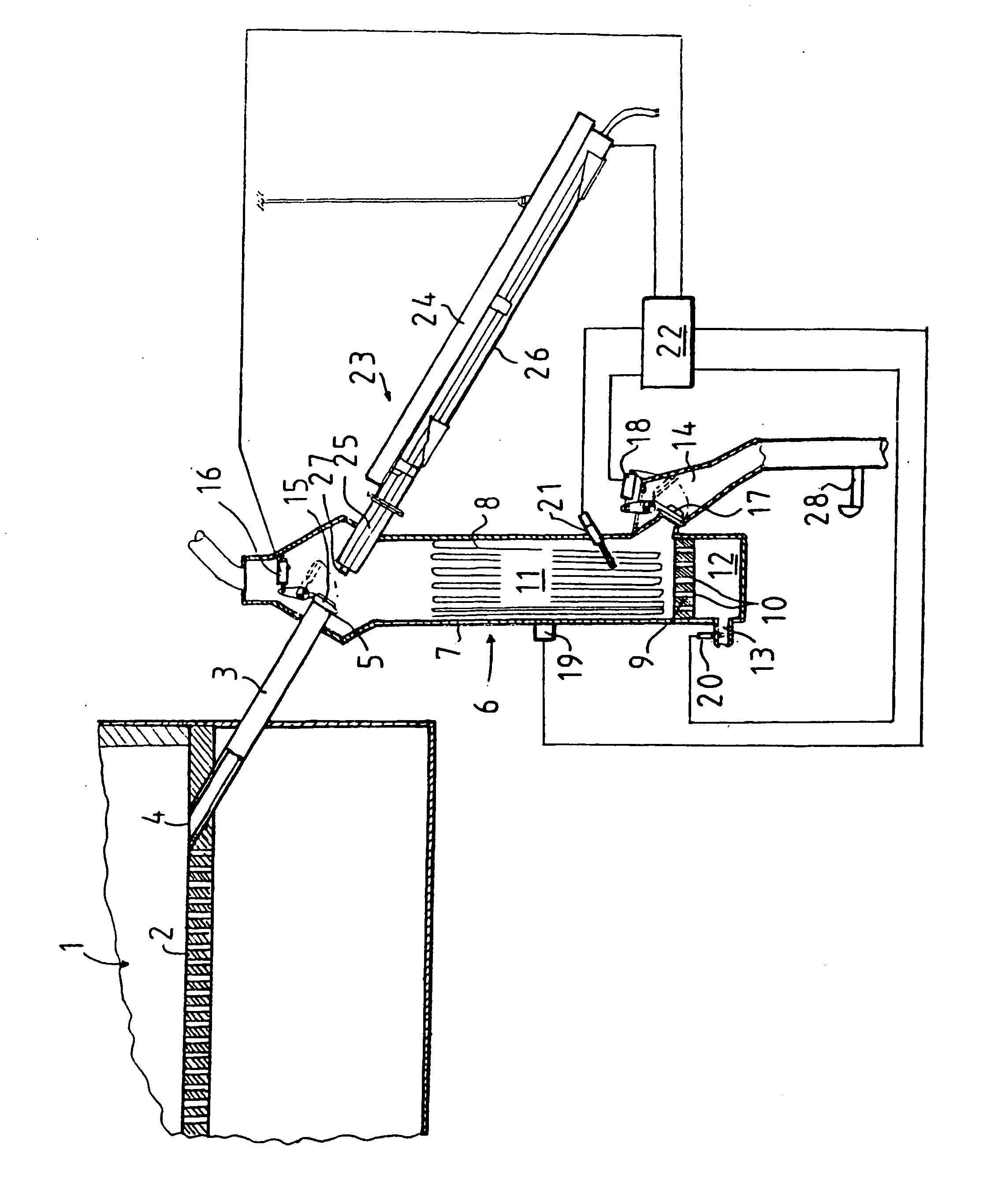
[0044]The below-described example embodiment of the invention relates to calcination of zinc concentrate in connection with hydrometallurgic zinc production. The purpose of the calcination of the concentrate is to convert sulfidic zinc into a soluble form before a solution treatment. This is accomplished in a fluidized bed furnace where, after ignition, the concentrate bed is oxidized at a temperature of about 900° C.-1000° C.

[0045]Although the invention is described here in connection with zinc production, it is applicable for any other purpose where fluidized bed furnaces are used and a hot particulate solid material is to be cooled to a lower temperature before being passed on for further treatment. Thus, the fluidized bed furnace may be e.g. a fluidized bed furnace intended for power plant use or the like.

[0046]From the calcining kiln, the calcine produced is removed at a rate of 5-8 t / h, most of which comes out by overflow of the calcining kiln while some of it drifts out with ...


PUM

PropertyMeasurementUnit
temperatureaaaaaaaaaa

Abstract

The invention relates to a method and an apparatus for cooling a material to be removed from the grate of a fluidized bed furnace. Material at a high temperature is passed from the grate of the fluidized bed furnace into a fluidized bed cooler in charges of a given size by measuring the quantity of the material accumulating in the fluidized bed cooler. When the quantity of the material in the cooler has reached a predetermined limit value, the supply of material into the fluidized bed cooler is prevented. The charge is cooled in the fluidized bed cooler by fluidization air and via heat transfer into a cooling liquid circulation system and the temperature of the charge is measured. The charge is removed when the temperature of the charge has fallen to a predetermined limit value. The second end (5) of a supply conduit (3) is provided with a supply valve (15) actuated by a power means (16). A discharge conduit (14) is provided with a discharge valve (17) actuated by a second power means (18). Quantity detection means (19, 20) are provided to produce quantity data regarding the amount of material in a fluidized bed space (11), and temperature measuring means (21) are provided to produce temperature data. A control device (22) controls the first power means (16) to open and close the supply valve (15) and the second power means (18) to open and close the discharge valve (17) on the basis of the quantity data and temperature data and the predetermined limit values of quantity and temperature so that the loading of material into the fluidized bed space and its cooling and removal from the fluidized bed space take place in a charge-by-charge and cyclic manner.

Description

FIELD OF THE INVENTION[0001]The present invention relates to a method as defined in the preamble of claim 1. Moreover, the invention relates to an apparatus as defined in the pre-amble of claim 14.BACKGROUND OF THE INVENTION[0002]In prior art, specification U.S. Pat. No. 4,227,488 discloses an apparatus for cooling coarse material removed from the grate of a fluidized bed furnace. The apparatus comprises a supply conduit having an upper first end, which opens to the grate of the fluidized bed furnace to receive material to be cooled from the grate into the supply conduit. Further, the apparatus comprises a fluidized bed cooler. The fluidized bed cooler has a housing, into the upper part of which the lower second end of the supply conduit opens. The housing encloses an interior space for receiving the material. Connected to the housing are cooling liquid pipes for cooling the material in the interior space. The apparatus further comprises a second grate having a number of through hol...

Claims


Application Information

Patent Timeline
Patent Type & Authority Applications(United States)
IPC IPC(8): F27D15/02C10J3/52F22B31/00F23C10/24F27B15/09F27B15/16F27B15/18F27D9/00F27D19/00
CPCC10J3/523F22B31/0084F23C10/24F27B15/09C10J2300/1625F27B15/18F27D9/00F27D19/00F27B15/16F22B31/00F23C10/00
Inventor NYBERG, JENSKARTSALO, VESASIIRILA, HEIKKIPERALAHTI, HEIKKI
Owner OUTOTEC OYJ
Why Eureka
Try Eureka