Tilting Touch Control Panel

a touch control and touch technology, applied in the field of control panels, can solve the problems of requiring considerable finger motion, prone to wear and possible failure, and the interior of the device is not sealed,

Inactive Publication Date: 2008-08-28
ATMEL CORP
View PDF49 Cites 348 Cited by
  • Summary
  • Abstract
  • Description
  • Claims
  • Application Information

AI Technical Summary

Benefits of technology

[0033]According to another aspect of the invention there is provided a control panel for controlling a device is response to user indications, the control panel comprising, a position sensing element having a sensing surface, and a position interface circuit. The position interface circuit is operable to determine a position of an object on the sensing surface, when the object is applied to the sensing surface of the position sensing element. The control panel includes at least one pressure sensing device. The pressure sensing device and the sensing surface of the position sensing element are arranged with the effect that a displacement of the sensing surface with respect to the pressure sensing device in response to pressure applied by the object is detectable by the pressure sensing device.

Problems solved by technology

This means the interior of the device is not sealed.
Accordingly, dirt and liquid may enter the device and cause damage.
In addition, the mechanical nature of the tilting mechanism is prone to wear and possible eventual failure.
Finally, the mechanism requires considerable finger motion to activate a function, because after performing a scrolling motion on the sensing surface the user must then locate a switch to press, causing the user to lift their finger and move it to one of the available switches.
This action could also cause additional unwanted scrolling action since the user's finger often does not lift off the sensing surface in a purely perpendicular motion, resulting in an unintended menu selection.
However, the design still has the disadvantage in that the user must locate a switch with a finger after a scrolling motion which could result in an error in menu selection.
The number of switches provided also means that such control panels are more difficult to manufacture requiring additional manufacturing steps.
Performance of both types is adversely affected by the requirement for the user to locate a switch to ‘enter’ a function after the scrolling selection is performed which can result in additional finger motion and errors.
Furthermore, because the touchpad is physically separate from the frame, gaps are left which leave the touchpad and the frame vulnerable to penetration by dirt and liquid.
Although the arrangement can determine a position and a pressure applied by a user input, the system is complicated.
Moreover, the system is concerned primarily with measuring a continuous range of input pressures and because the system is implemented using semi-conductor sensors, the range of detectable input pressures that can be accurately detected is limited.
Although enabling both the position of a user input and the movement of the touchpad to be detected, this system does not enable the detection of an individual actuating pressure, which can detect a user input pressure above a pre-determined threshold value.
Furthermore, the disclosed system requires a number of movement sensors to detect the movement of the frame, which can add to the cost and complexity of the input device as a whole.
In addition, since the touchpad is physically separate from the rest of the device, gaps are left which leave the device vulnerable to penetration by dirt and liquid.

Method used


Image

  • Tilting Touch Control Panel
  • Tilting Touch Control Panel
  • Tilting Touch Control Panel

Examples


Embodiment Construction

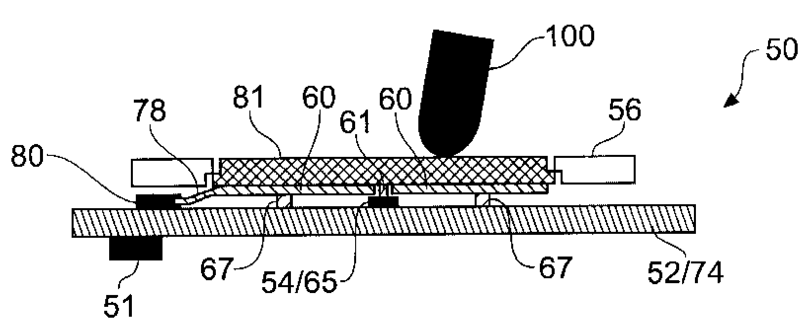
[0058]FIG. 3 schematically shows in section view a control panel 50 for controlling a device, e.g. a portable music player, mobile telephone, or any other appliance, according to an embodiment of the invention. A PSE 60 of any operable basis in physics (such as capacitance or other form of impedance measurement, optical, acoustic, piezoelectric etc) lies under a user surface 62, said surface being designed to be touched and pressed by a user. Rigid carrier plate 58 is supported by resilient material 64 which is compressed under pressure between 58 and PCB 52 on which the assembly is supported. Electrical, optical or acoustic connections to 60 are not shown. Travel limiter appendage ridge or posts 59 extends below the assembly to prevent damage to the assembly from over-pressure. A PSD 54 is compressed by appendage 61, which acts as a force concentrator, when the user 100 applies force anywhere along surface 62.

[0059]Optional seal 55 provides a moisture and dust barrier to the assemb...


PUM


Abstract

A control panel for controlling a device in response to user indications, the control panel comprising, a position sensing element (60) having a sensing surface, and a position interface circuit (76). The position interface circuit (76) is operable to determine a position of an object (100) on the sensing surface, when the object (100) is applied to the sensing surface of the position sensing element (60). At least one pressure sensing device (54, 66) and the sensing surface of the position sensing element (60) are arranged with the effect that a displacement of the sensing surface with respect to the pressure sensing device in response to the pressure applied by the object is detectable by the pressure sensing device. As such, in one example, the position interface circuit (76) is operable to identify one or more of a plurality of user indicated signals by correlating the position of the object on the sensing surface with a pressure detected by the pressure sensing device. The sensing surface may include pre-designated and pre-determined locations representing virtual buttons so that by determining whether the object is at one of a plurality of pre-determined locations on the sensing surface of the position sensing element, the position interface circuit (76) can identify the user indicated signal by correlating the position of the object at one of the predetermined locations with the detected pressure, each of the pre-determined location corresponding to one of the plurality of user indicated signals.

Description

FIELD OF THE INVENTION[0001]The invention relates to control panels for controlling a device in response to a user's input, in particular the invention relates to a control panel having both touch sensitive and mechanical input means.BACKGROUND OF THE INVENTION[0002]There is an increasing demand for compact and user-friendly control panels for many devices, for example for devices such as portable media players, digital cameras, mobile telephones and so forth. These devices are becoming smaller and are being provided with more functionality. To make best use of this increased functionality it is important that the control panel presented to the user (i.e. the user interface) is ergonomic, simple and intuitive to use, and allows the user to quickly access the functions of the device. There is also a demand for control panels which are both aesthetically pleasing and robust yet simple to manufacture.[0003]It is known for control panels to include both touch sensitive inputs (e.g. capa...

Claims


Application Information

Patent Timeline
Patent Type & Authority Applications(United States)
IPC IPC(8): G06F3/041
CPCG06F3/02G06F3/0338G06F3/03547G06F3/041H03K17/962G06F3/044G06F3/0488G06F2203/04105G06F3/0414G06F3/04164
Inventor PHILIPP, HARALDHINSON, NIGEL S. D.ARD, CHRISTOPHER K.
Owner ATMEL CORP
Why Eureka
Try Eureka