Rotational-molded resin fuel tank

a technology of resin fuel tank and rotating molding, which is applied in the direction of synthetic resin layered products, transportation and packaging, and other domestic articles, can solve the problems of poor fluidity of high-density polyethylene resin, disadvantage of motorcycle fuel tank, and low mold transferability, and achieves superior weathering resistance, low temperature impact resistance, and low resistance to gasoline permeability.

Inactive Publication Date: 2008-08-28
HONDA MOTOR CO LTD
View PDF6 Cites 8 Cited by
  • Summary
  • Abstract
  • Description
  • Claims
  • Application Information

AI Technical Summary

Benefits of technology

[0012]Further, a resin fuel tank of a multi-layer structure having at least inner and outer layers can be produced by rotational molding of different resins within one and the same mold. Additionally, the adhesion between the inner and outer layers can be enhanced by rotational molding.
[0014]Further, the outer layer may be formed using a polyethylene resin which is superior in weathering resistance and low temperature impact resistance and is relatively inexpensive, but is inferior in resistance to gasoline permeability, while the inner layer may be formed of a polyamide resin which is superior in resistance to gasoline permeability but is inferior in weathering resistance and low temperature impact resistance and is high in material cost, or a copolymer of the polyamide resin with a polyethylene resin. Therefore, the performance of the whole of the resin fuel tank can be improved by complementarily utilizing the characteristics of those resins. In the case of forming the inner layer with use of a copolymer of both polyamide resin and polyethylene resin, the bonding of the inner layer with the outer layer of polyethylene resin becomes stronger.
[0015]Additionally, there may be used, as the resin of the inner layer, a lower melting resin included in the same system of resins as that of the inner layer resin, whereby the inner layer difficult to be heated can be molded at a relatively low temperature. Consequently, it becomes easier to form a resin fuel tank of a multi-layer structure by rotational molding.
[0016]There is also provided a three-layer structure having an intermediate layer between the inner and outer layers, wherein the outer layer is formed of a resin superior in weathering resistance and low temperature impact resistance, the inner layer is formed of a resin superior in resistance to gasoline permeability, and the intermediate layer is formed of a resin superior in adhesion to both inner and outer layers. Consequently, the bonding among the multiple layers can be made stronger.
[0017]Further, in the three-layer resin fuel tank described above, since the outer, inner, and intermediate layers are formed of a polyethylene resin, a fluorine resin, and a polyamide resin, respectively, not only excellent appearance resistance to gasoline permeability can be ensured by the polyethylene resin of the outer layer and the fluorine resin of the inner layer, respectively, but also the bonding between the inner and outer layers can be strengthened by the polyamide resin of the intermediate layer. Besides, the polyamide resin of the intermediate layer complements the resistance to gasoline permeability of the fluorine resin and thus it is possible to improve the resistance to gasoline permeability of the whole of the resin fuel tank.

Problems solved by technology

Besides, a high-density polyethylene resin is poor in fluidity and is also low in mold transferability because blowing of air is performed at a relatively low pressure.
This is sometimes disadvantageous to the fuel tank of a motorcycle, where the appearance is important.
Further, such a relatively complicated shape as the fuel tank of a motorcycle is difficult to undergo blow molding and morphological restrictions have sometimes occurred heretofore.

Method used


Image

  • Rotational-molded resin fuel tank
  • Rotational-molded resin fuel tank
  • Rotational-molded resin fuel tank

Examples


Embodiment Construction

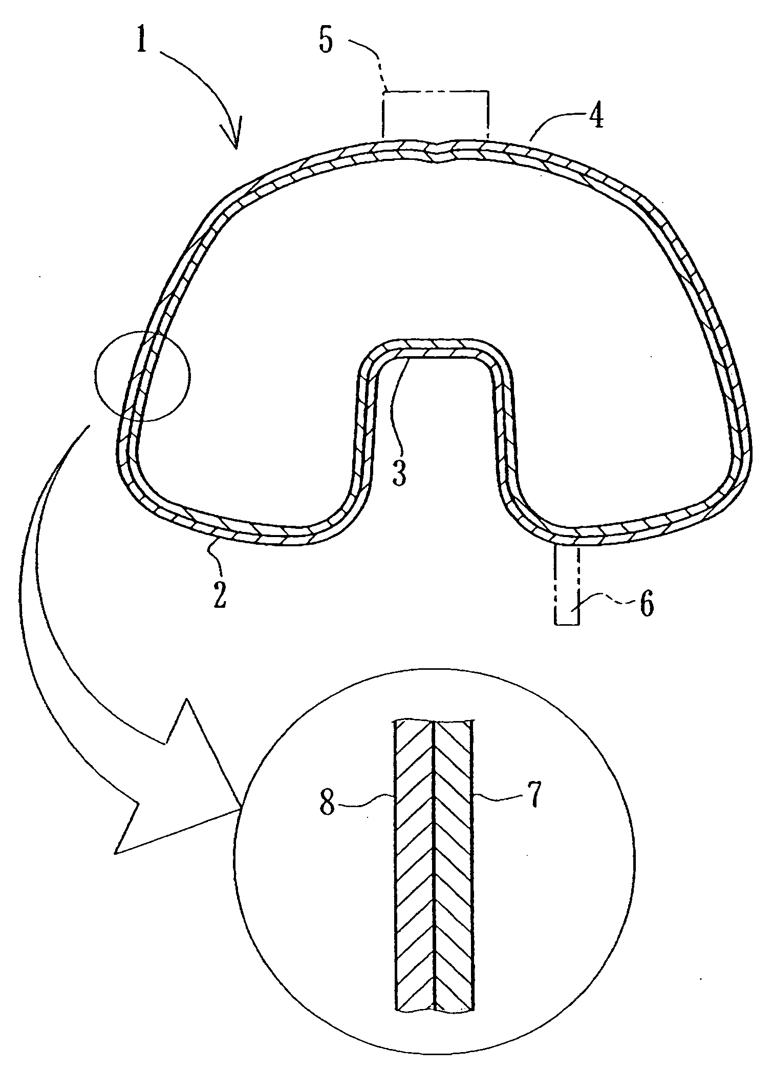
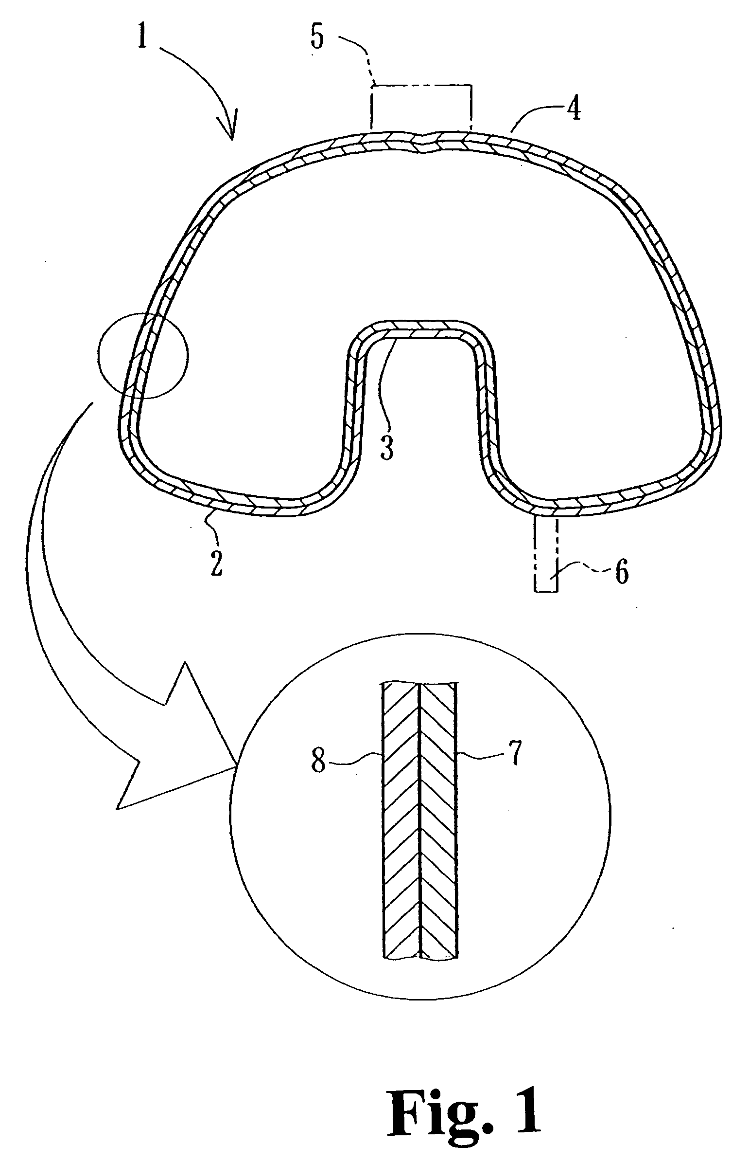
[0023]An embodiment of the present invention will be described hereinunder with reference to the drawings. FIG. 1 is a sectional view of a resin fuel tank for gasoline in a motorcycle to which the present invention is applied. The resin fuel tank, indicated at 1, is formed in the shape of a vessel as a whole and a generally inverted U-shaped groove 3 is formed longitudinally and centrally of a bottom 2 of the tank. Thus, the tank 1 has a relatively complicated shape. A body frame (not shown) is fitted in the groove 3. Further, a fuel inlet 5 and a discharge pipe 6 are integrally provided in an upper portion 4 and the bottom 2, respectively.

[0024]As shown in an enlarged portion of the same figure, the resin fuel tank 1 has a two-layer structure of an inner layer 7 and an outer layer 8. The inner layer 7 is formed of a resin superior in resistance to gasoline permeability, e.g., a polyamide resin or a copolymer thereof with a polyethylene resin. In the following description the polyam...


PUM

PropertyMeasurementUnit
melting temperatureaaaaaaaaaa
thicknessaaaaaaaaaa
temperatureaaaaaaaaaa

Abstract

A resin fuel tank having a two-layer structure of inner and outer layers is formed by rotational molding so as to be superior not only in appearance but also in weathering resistance, low temperature impact resistance and resistance to gasoline permeability.

Description

FIELD OF THE INVENTION[0001]The present invention relates to a resin fuel tank in a motorcycle or the like and more particularly to a resin fuel tank having a multi-layer structure obtained by rotational molding.BACKGROUND OF THE INVENTION[0002]It is publicly known to form a fuel tank for gasoline in a motorcycle or the like with use of resin. Blow molding using a high-density polyethylene resin is known as a method for producing such a resin fuel tank. As an example there is known a resin fuel tank having two inner and outer layers, produced by laminating resin materials of different colors into two layers and by subsequent blow molding (see Japanese Patent Laid-Open No. Hei 7-125665 (JP '655)).[0003]Resin fuel tanks have recently been required to have improved resistance to gasoline permeability. This requirement can be met by forming a resin fuel tank of a multi-layer structure. However, if blow molding is performed as in JP '665, there occurs surface roughening or flow mark due ...

Claims


Application Information

Patent Timeline
Patent Type & Authority Applications(United States)
IPC IPC(8): B29C45/14
CPCB29C41/04Y10T428/1352B29C41/22B29L2031/7172B32B1/02B32B27/08B32B27/32B32B27/34B32B2250/02B32B2250/242B32B2307/558B32B2307/712B32B2307/7265B32B2605/08B29C41/06
Inventor FUJITAKA, NOBUOKOBAYASHI, AKIHITO
Owner HONDA MOTOR CO LTD
Why Eureka
Try Eureka