
Fine-Grained Power Management of Synchronous and Asynchronous Datapath Circuits

a datapath and power management technology, applied in the field of integrated circuit power management, can solve the problems of increasing software complexity, less of a power dissipation reduction than would otherwise be optimally achievable, and achieve the effect of reducing power dissipation

Active Publication Date: 2008-08-28
AVAGO TECH INT SALES PTE LTD
View PDF5 Cites 6 Cited by
  • Summary
  • Abstract
  • Description
  • Claims
  • Application Information

AI Technical Summary

Benefits of technology

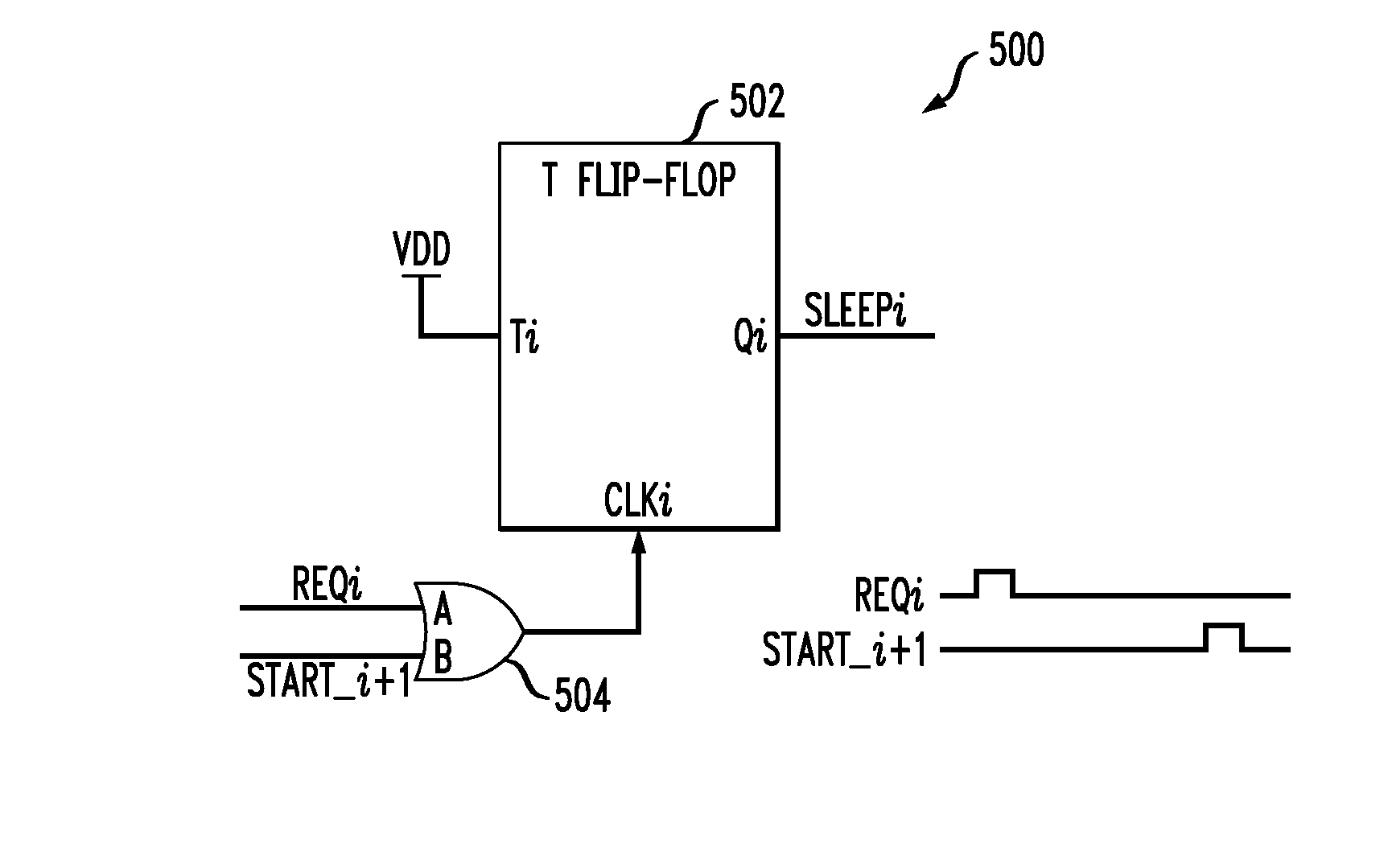
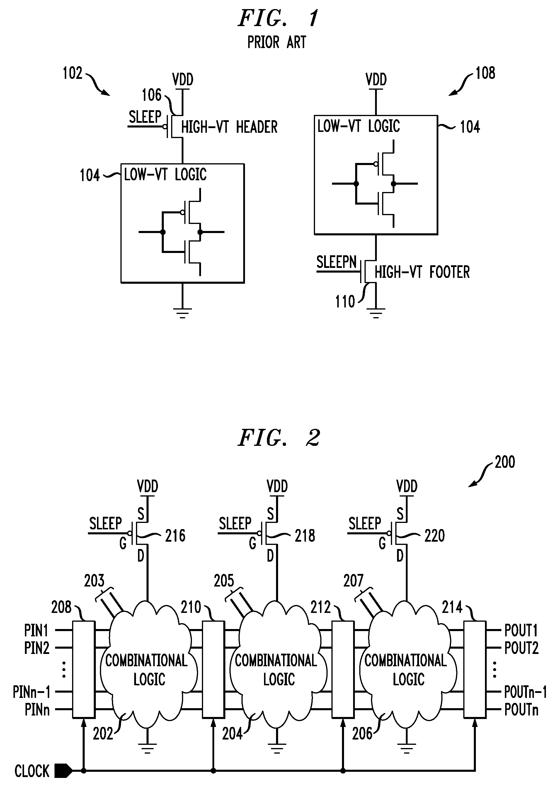
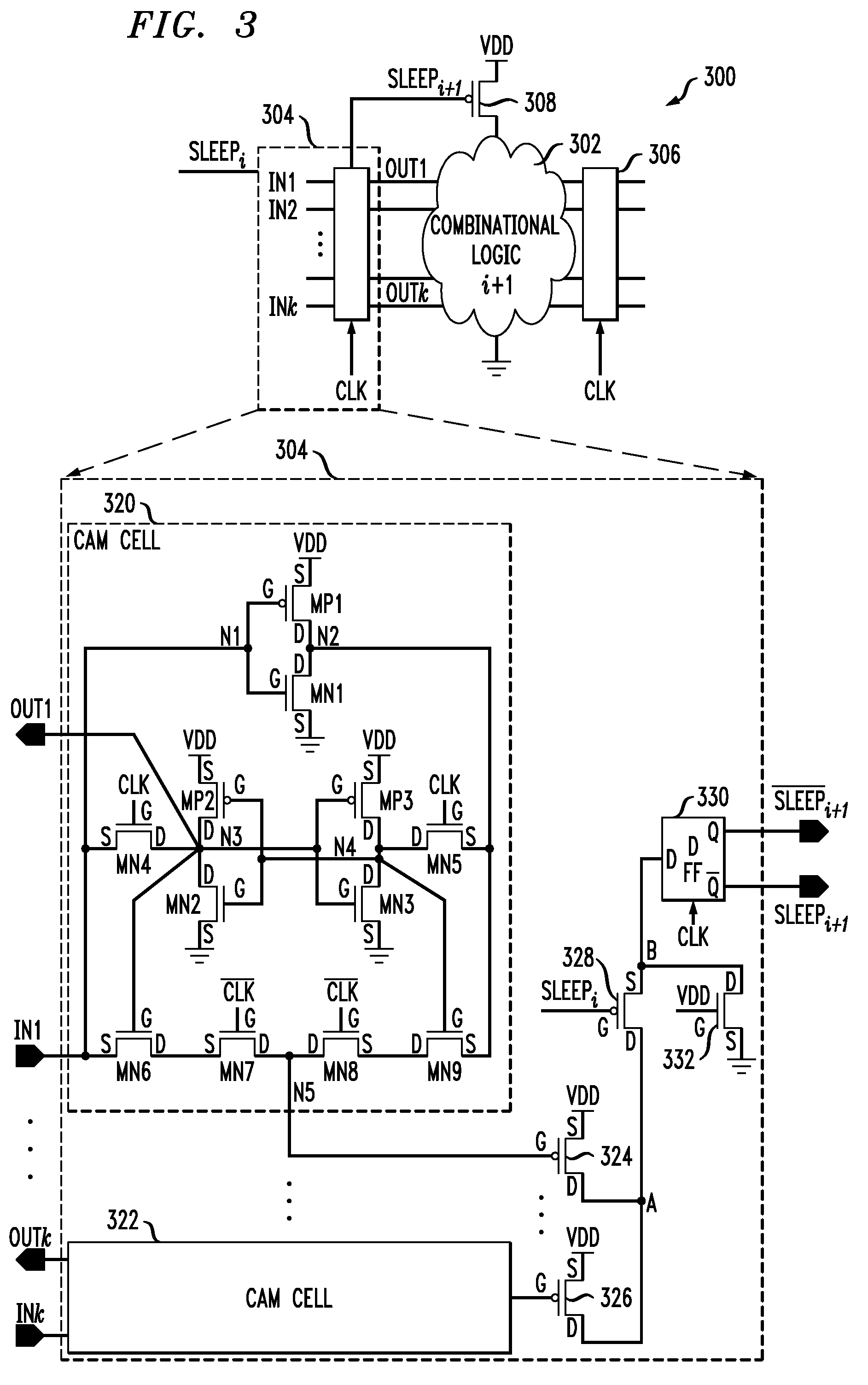
The present invention provides techniques for reducing power dissipation in a circuit employing combinational logic. The invention uses a fine-grained, bit-level approach to on-chip power management, which offers significant improvement over standard coarse-grained, system-level power management methodologies. A power management circuit is provided that includes a detector and a controller. The detector receives a first input signal and detects a logic state transition between a first logic state and a second logic state. The controller selectively disconnects the combinational logic circuit from a power supply when no logic transition of the first input signal is detected and connects it when a logic transition is detected. This results in significant reduction of power dissipation in the circuit.

Problems solved by technology

Unfortunately, these conventional approaches can significantly increase software complexity and / or cause non-optimal control signal generation.
In particular, by controlling the power management function at the system level (i.e., coarse-grained control), the aforementioned approaches may cause the circuit to be powered-up longer than necessary, resulting in less of a reduction in power dissipation what would otherwise be optimally attainable.

Method used


Image

  • Fine-Grained Power Management of Synchronous and Asynchronous Datapath Circuits
  • Fine-Grained Power Management of Synchronous and Asynchronous Datapath Circuits
  • Fine-Grained Power Management of Synchronous and Asynchronous Datapath Circuits

Examples


Embodiment Construction

[0018]The present invention will be described herein in the context of illustrative pipelined circuit architectures. While techniques of the invention may be employed with synchronous and / or asynchronous pipelined circuits, it should be understood that the present invention is not limited to these or any particular circuit arrangements, or to pipelined circuitry in general. Rather, the invention is more generally applicable to techniques for advantageously reducing power dissipation in a circuit including one or more combinational logic blocks. Embodiments of the invention, at least a portion of which may be implemented in an integrated circuit, utilize a fine-grained, bit-level approach to on-chip power management, thereby advantageously reducing power dissipation in a circuit compared to standard power management methodologies which utilize system level (e.g., coarse-grained) control.

[0019]Although implementations of the present invention are described herein with specific referen...


PUM


Abstract

A power management circuit is provided for controlling power dissipation in at least one combinational logic circuit. The power management circuit includes a detector operative to receive at least a first input signal to the combinational logic circuit and to detect a transition of the first input signal between a first logic state and a second logic state. The detector generates a control signal indicative of whether or not a transition of the first input signal has occurred. The power management circuit further includes a controller operative to receive the first control signal generated by the detector and to selectively disconnect the first combinational logic circuit from a power supply to the first combinational logic circuit when no logic transition of the first input signal is detected between a preceding computational cycle and a present computational cycle of the first combinational logic circuit, and to connect the first combinational logic circuit to the power supply when a logic transition of the first input signal is detected.

Description

FIELD OF THE INVENTION[0001]The present invention relates generally to integrated circuit (IC) power management, and more particularly relates to power management of logic circuits.BACKGROUND OF THE INVENTION[0002]Power management in integrated circuits is becoming increasingly more important, particularly in power-intensive 65 nanometer (nm) and smaller IC fabrication process technologies. In order to reduce overall power consumption in the IC, it is known to place one or more logic circuits in the IC into a “Power-down” (e.g., Sleep or Standby) mode when they are not being used. For example, multiple-threshold complementary metal-oxide-semiconductor (MTCMOS) devices use high-threshold voltage (VT), low-leakage header and / or footer switches to control leakage power dissipation.[0003]FIG. 1 illustrates a first circuit 102 including a low-VT logic circuit 104 which is selectively connected to a corresponding power supply, VDD, via a high-VT, low-leakage PMOS device 106 functioning as...

Claims


Application Information

Patent Timeline
Patent Type & Authority Applications(United States)
IPC IPC(8): G05F1/10
CPCH03K19/0016
Inventor CHAKRABORTY, KANADSTRAUSS, STEVEN E.XU, BINGXIONG
Owner AVAGO TECH INT SALES PTE LTD
Learn More