Oscillator

a technology of oscillator and oscillator body, which is applied in the field of oscillator, can solve the problems of large size of the oscillator, the temperature dependence of the oscillation frequency is worse than that and the inability of the crystal resonator to meet the recent demand for further downsizing of the electronic device, etc., and achieves the effect of small siz

Inactive Publication Date: 2008-08-28
SEIKO INSTR INC
View PDF7 Cites 86 Cited by
  • Summary
  • Abstract
  • Description
  • Claims
  • Application Information

AI Technical Summary

Benefits of technology

[0016]According to the present invention, the capacitor that is connected to the output oscillator circuit is designed so as to change the capacitance with respect to the temperature. As a result, it is possible to provide an oscillator which shows little change in the frequency with respect to the temperature and which automatically corrects the change in oscillation frequency of the oscillator caused by the environmental temperature. Also, since the capacitor is located adjacent to the MEMS resonator and manufactured in the same process as that of the MEMS resonator, it is possible to correct the oscillation frequency of the oscillator by precise...

Problems solved by technology

However, it has been also proved that the crystal resonator cannot sufficiently satisfy a recent demand for further downsizing of the electronic devices.
In the MEMS oscillator according to the above conventional art, however, there arises such a problem that the temperature dependency of the oscillation frequency is worse than that of a crystal resonator.
To correct the temperature dependency a tempe...

Method used


Image

  • Oscillator
  • Oscillator
  • Oscillator

Examples


first embodiment

[0026]Hereinafter, a description will be given of an embodiment of the present invention with reference to the accompanying drawings.

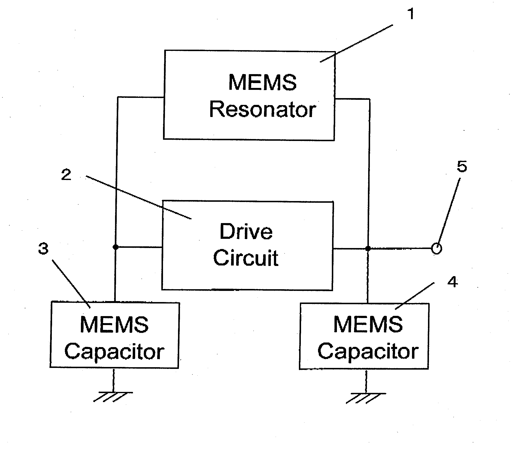
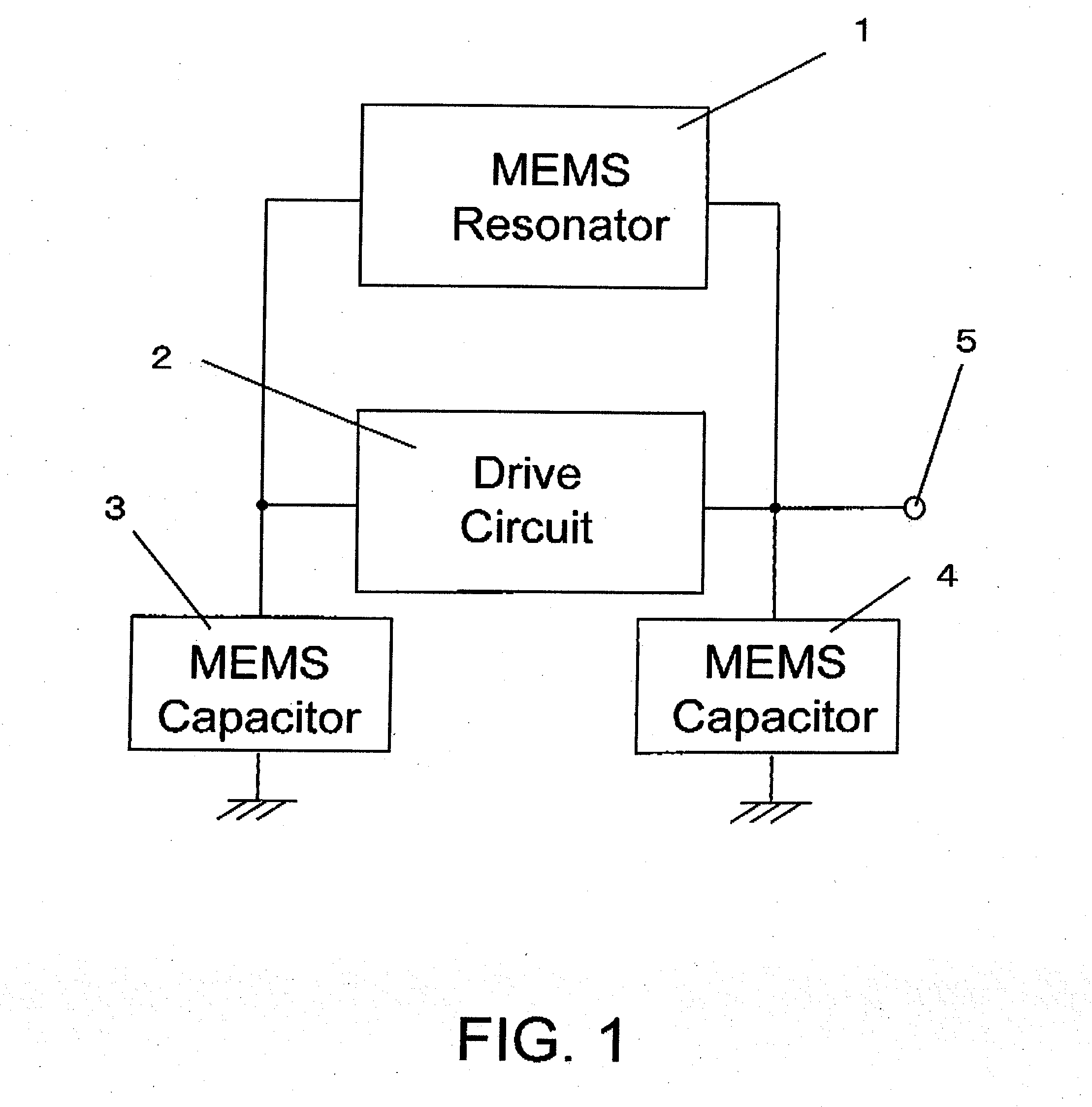
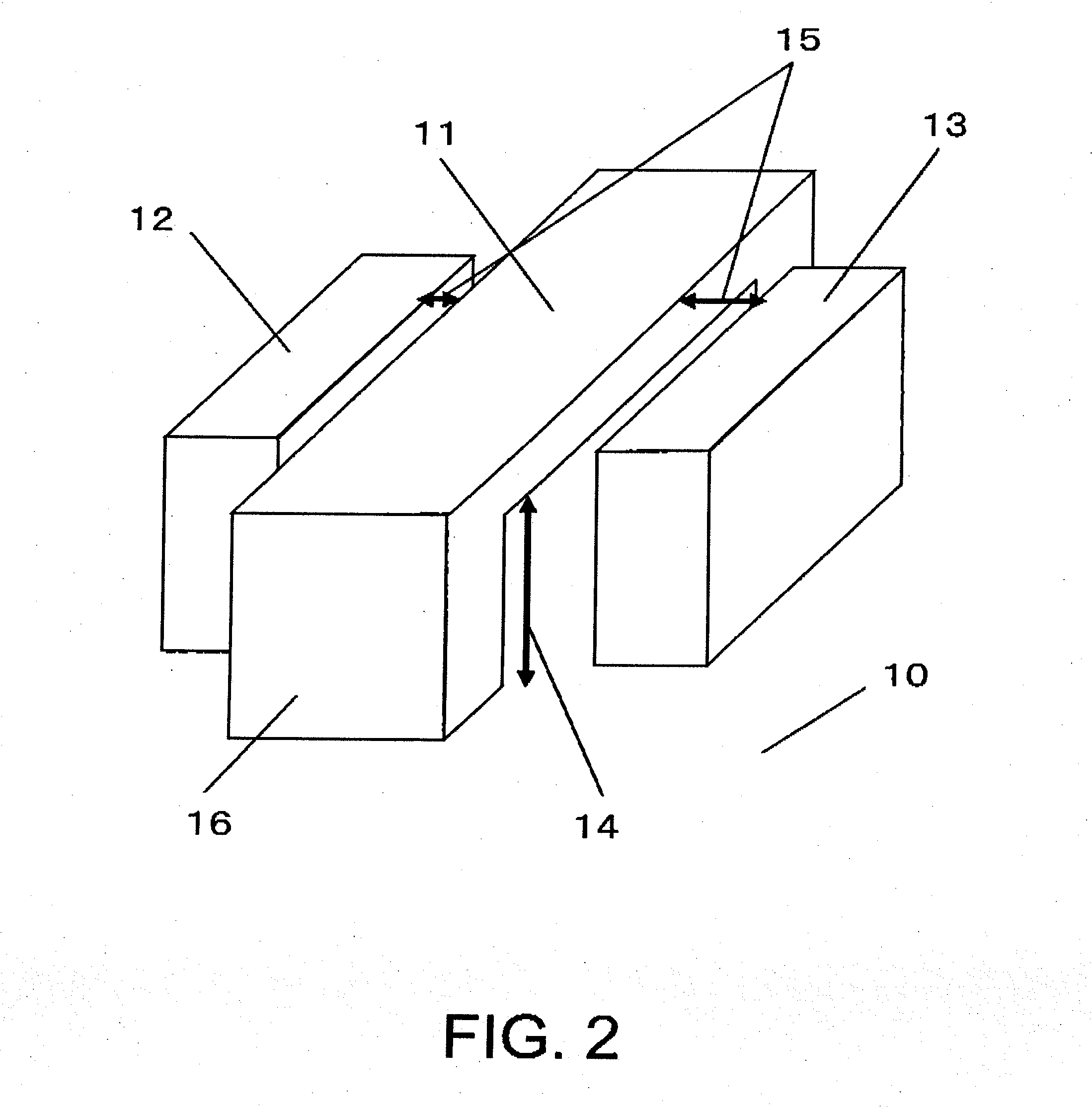
[0027]FIG. 1 is a block diagram showing an oscillator according to an embodiment of the present invention. As shown in the figure, the oscillator includes a MEMS resonator 1, an output oscillator circuit 2, and MEMS capacitors 3 and 4. Also, as shown in FIG. 2, the MEMS resonator 1 includes an oscillation beam 11, a drive electrode 12, and a sense electrode 13. The sense electrode 13 of the MEMS resonator 1 is connected to the MEMS capacitor 3 and an input terminal of the output oscillator circuit 2. The drive electrode 12 of the MEMS resonator 1 is connected to the MEMS capacitor 4, an output terminal of the output oscillator circuit 2, and an output terminal 5 of the oscillator.

[0028]The block diagram of the oscillator shown in FIG. 1 is constructed based on a Colpitts oscillator circuit, but is not necessarily limited to this configuration. The feat...

second embodiment

[0047]An oscillator according to another embodiment of the present invention will be described in detail.

[0048]In the frequency temperature characteristic of the MEMS resonator 1, as shown in FIG. 8, the resonance frequency of the MEMS resonator decreases when the temperature rises. Also, a relationship between the temperature and the frequency is not linear but is quadratic. Up to now, in order to improve the frequency temperature characteristic of the MEMS resonator, there have been used the methods disclosed in UP 2006 / 0033594 A1 and US 2002 / 0069701 A1. In those methods, the linear component of the frequency temperature characteristic is reduced, but the effect of reducing the quadratic component of the temperature characteristic is small. Under the circumstances, in another embodiment of the present invention, the capacitance values of the MEMS capacitors 3 and 4 which are connected to the input / output terminals of the output oscillator circuit 2 show quadratic change due to tem...


PUM


Abstract

Provided is an oscillator including: a MEMS resonator for mechanically vibrating; an output oscillator circuit for oscillating at a resonance frequency of the MEMS resonator to output an oscillation signal; and a MEMS capacitor for changing a capacitance thereof caused by a change in a distance between an anode electrode and a cathode beam according to an environmental temperature.

Description

REFERENCE TO THE RELATED APPLICATIONS[0001]This application claims priority under 35 U.S.C. §119 to Japanese Patent application No. JP2007-045008 filed Feb. 26, 2007, the entire content of which is hereby incorporated by reference.BACKGROUND OF THE INVENTION[0002]1. Field of the Invention[0003]The present invention relates to an oscillator using a MEMS technology.[0004]2. Description of the Related Art[0005]Under the increasing demand for reduction in size and increase in accuracy of electronic devices such as personal computers and wireless mobile devices represented by cellular phones, a small and stable high frequency signal source is inevitable in these electronic devices. A crystal resonator is a representative electronic part that satisfies the demand. It is known that the crystal resonator has an extremely high resonance sharpness (that is, Q value) which is an index of the oscillation device quality, and which exceeds 10,000 owing to the excellent crystal stability. This is ...

Claims


Application Information

Patent Timeline
IPC IPC(8): H03B1/00
CPCH03B5/30
Inventor YOSHIDA, YOSHIFUMIKIMURA, FUMIO
Owner SEIKO INSTR INC
Why Eureka
Try Eureka