Method For Light Propagation Time Measurement

a technology of light propagation time and measurement method, which is applied in distance measurement, instruments, surveying and navigation, etc., can solve the problems of difficult to determine the exact point of incidence, still more difficult, and the rise of sending leds

Active Publication Date: 2008-08-28
REIME GERD
View PDF3 Cites 7 Cited by
  • Summary
  • Abstract
  • Description
  • Claims
  • Application Information

AI Technical Summary

Benefits of technology

[0031]It is advantageous to control the phase shift between the first light signal over the light path and the second signal from the further transmitter or the compensation element by means of a control loop in which the difference value of the clock pulse alternation signa...

Problems solved by technology

Hereby, the following problem with the state of the art occurs: If one applies a pulsed voltage to a light emitting diode, then it lights up at the rhythm of this applied voltage.
In order to measure the distance of the reflecting object, the use of a light propagation time measurement between the sent and the received signal is of course possible, but in the case of the above mentioned very small received current in the photodiode, it is very difficult to determine the exact point of incidence.
Making it still more difficult is the fact that the signal entering the photodiode or the amplifier connected thereto does not produce the flank steepness with which it ...

Method used


Image

  • Method For Light Propagation Time Measurement
  • Method For Light Propagation Time Measurement
  • Method For Light Propagation Time Measurement

Examples


Embodiment Construction

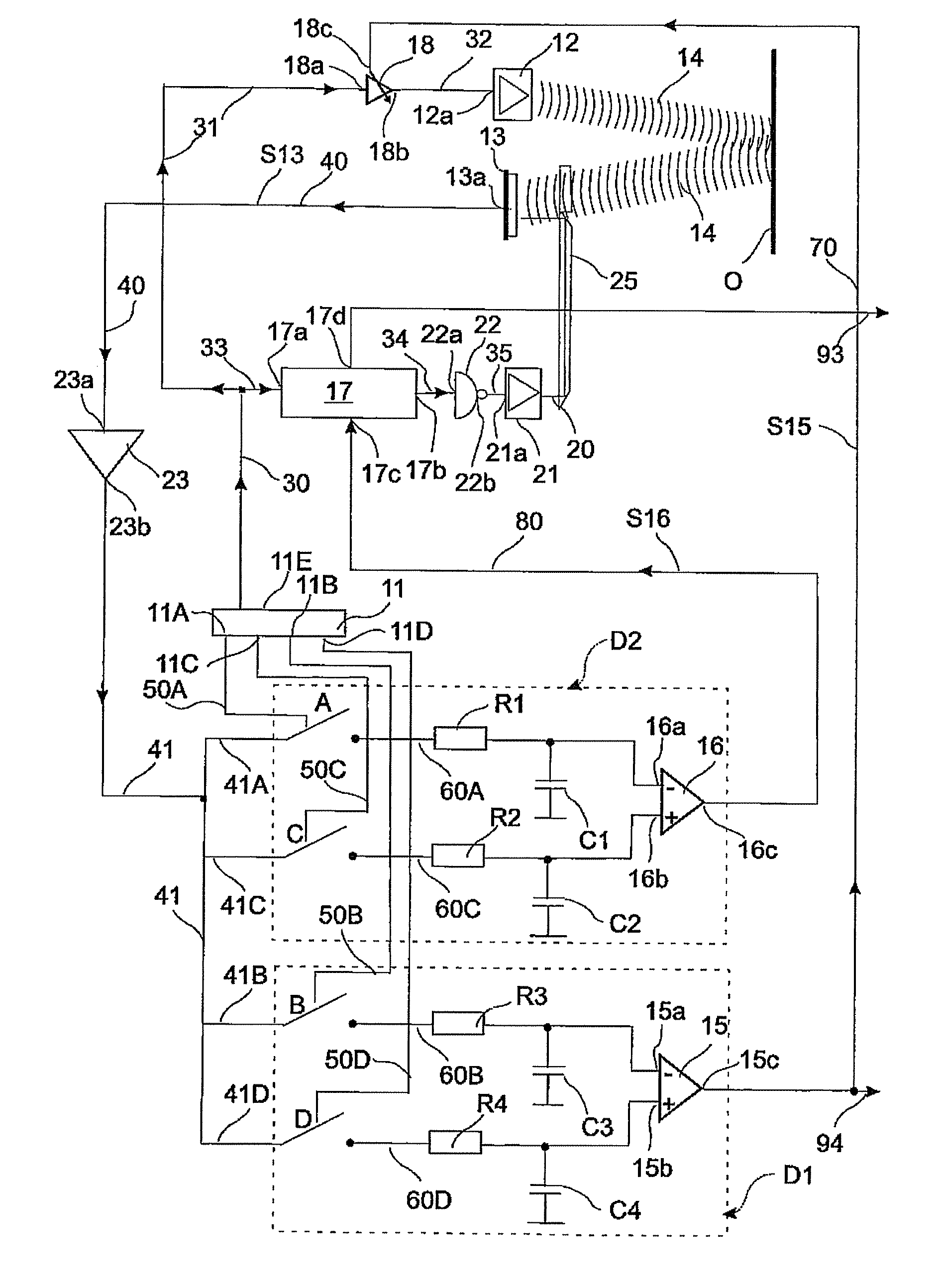
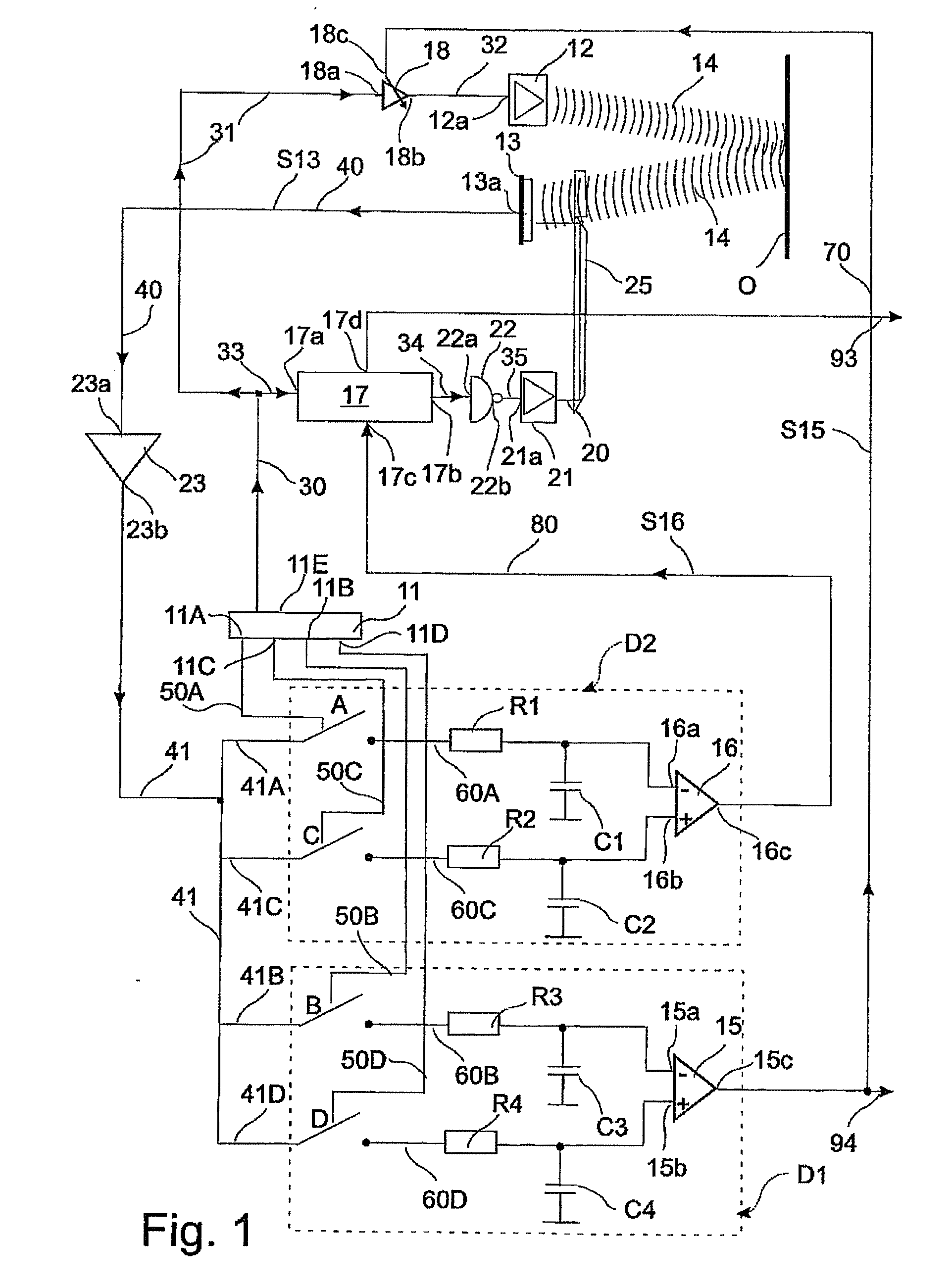
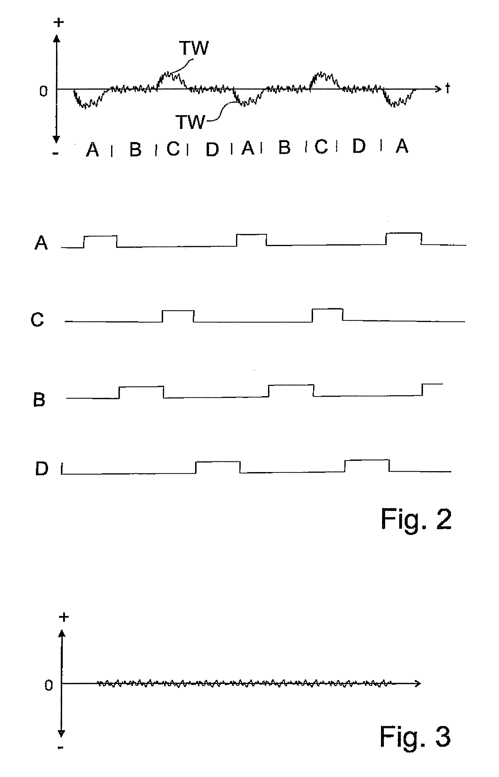
[0044]The invention is now described in more detail in exemplary manner with reference to the accompanying drawings. Nevertheless, the exemplary embodiments are merely examples which are not intended to restrict the inventive concept to a certain arrangement.

[0045]Before the invention is described in detail, it should be pointed out that it is not restricted to the particular components of the circuit or the particular method steps since these components and methods can vary. The terms used here are merely intended to describe special embodiments and are not used in a restrictive manner. If, in addition, the singular or indefinite article is used in the description and in the Claims, this also refers to a plurality of these elements as long as the general context is not unambiguously making something else clear.

[0046]The invention enables a distance measurement to be made which permits of an accurate light propagation time measurement that is free of extraneous light problems, indep...


PUM


Abstract

In a method and a device for light propagation time measurement, in particular for cameras, a light signal clocked by a clock controller (11) is transmitted from at least one transmitter (12) into a light path (14) via a retroreflective object (O) to a receiver (13) for detecting the alteration of the first light signal on account of the approach, presence and/or distance of the object (O). At the receiver, the received signal is determined from the light path on account of the first light signal and, in order to determine the propagation time, is cyclically compared in a comparator (15) with a second signal which is clocked by the clock controller (11) and which is produced without the light path (14), in order to generate a comparison value at the output of the comparator (15), which value is used for regulating the amplitude values of the transmitted signal and/or of the second signal such that the received signal and the second signal at least at the input of the comparator are substantially identical in magnitude. In parallel, the clock change signal (TW)—occurring during the clock change and corresponding to the light propagation time—between received signal from the light path (14) and second signal, given the magnitude of received signal from the light path (14) and second signal corrected to substantially identical magnitude at the input of the comparator (15), is detected cyclically. A difference value (S16) is determined by comparison of the clock change signals (TW) between received signal and second signal according to their amplitude in a further comparator (16). The difference value (S16) is altered by means of a phase shifter (17) for altering the phase delay of the phase of received signal and second signal until the difference value (S16) becomes minimal, preferably zero. The delay of the phase shifter that occurred given a minimal difference value is used for determining the light propagation time. A method for light propagation time measurement which can also operate with more favourable components and lower-frequency amplifiers is created as a result.

Description

CROSS REFERENCE TO RELATED APPLICATIONS[0001]The present application claims the priority of the German Patent Applications 10 2005 036 354.7 filed on 29.07.2005, and 10 2005 045 993.5 filed on 27.09.2005, the disclosure whereof is hereby expressly incorporated into the subject matter of the present application by reference.TECHNICAL FIELD OF THE INVENTION[0002]The invention relates to a method and a device for light propagation time measurement.BRIEF DISCUSSION OF RELATED ART[0003]The distance of a reference object relative to other objects has to be determined in many fields of application. One such field of employment is, above all, that of camera systems, e.g. in the automotive field too or in the field of robotics.[0004]Hereby, the following problem with the state of the art occurs: If one applies a pulsed voltage to a light emitting diode, then it lights up at the rhythm of this applied voltage. A reflecting object can reflect the radiated light power to a photodiode that is pr...

Claims


Application Information

Patent Timeline
IPC IPC(8): G01S17/08G01S7/4865G01S17/10
CPCG01S7/487G01S7/4865G01S17/10
Inventor REIME, GERD
Owner REIME GERD
Why Eureka
Try Eureka