Device For Reconfigurable Processing Optical Beams

a reconfigurable processing and optical beam technology, applied in the direction of measurement devices, instruments, material analysis, etc., can solve the problems of high alignment constraints, difficult assembly of the different mobile optical deflection elements, and limited movement range of the devi

Inactive Publication Date: 2008-08-28
COMMISSARIAT A LENERGIE ATOMIQUE ET AUX ENERGIES ALTERNATIVES
View PDF5 Cites 3 Cited by
  • Summary
  • Abstract
  • Description
  • Claims
  • Application Information

AI Technical Summary

Benefits of technology

[0011]In particular, one purpose is to propose a reconfigurable optical processing device of easy construction, which is low-cost to produce, has low electricity consumption and switching time, and which can be easily adapted over time to suit user needs.
[0026]Each mobile optical deflection element has digital control (as opposed to analog control), which allows for reduced electricity consumption, only requires displacements over very short travel lengths (in the order of one micrometer or a dozen micrometers) and reduces switching times, these times possibly being less than a millisecond.

Problems solved by technology

The assembly of the different mobile optical deflection elements, of the output ports and of the diffraction grating is difficult, alignment constraints are high.
Depending on the configuration of the optical transforming device, its range of movement may be fairly extensive, which requires a complex and relatively slow actuator system.
In addition, the presence of the complex actuator system prevents the optical transforming device from being interchangeable.
The movement of the support can only be obtained with an actuator device which is complex and relatively slow.

Method used


Image

  • Device For Reconfigurable Processing Optical Beams
  • Device For Reconfigurable Processing Optical Beams
  • Device For Reconfigurable Processing Optical Beams

Examples


Embodiment Construction

[0010]The purpose of the present invention is to propose an optical processing device which does not have the above-mentioned limitations and difficulties.

[0011]In particular, one purpose is to propose a reconfigurable optical processing device of easy construction, which is low-cost to produce, has low electricity consumption and switching time, and which can be easily adapted over time to suit user needs.

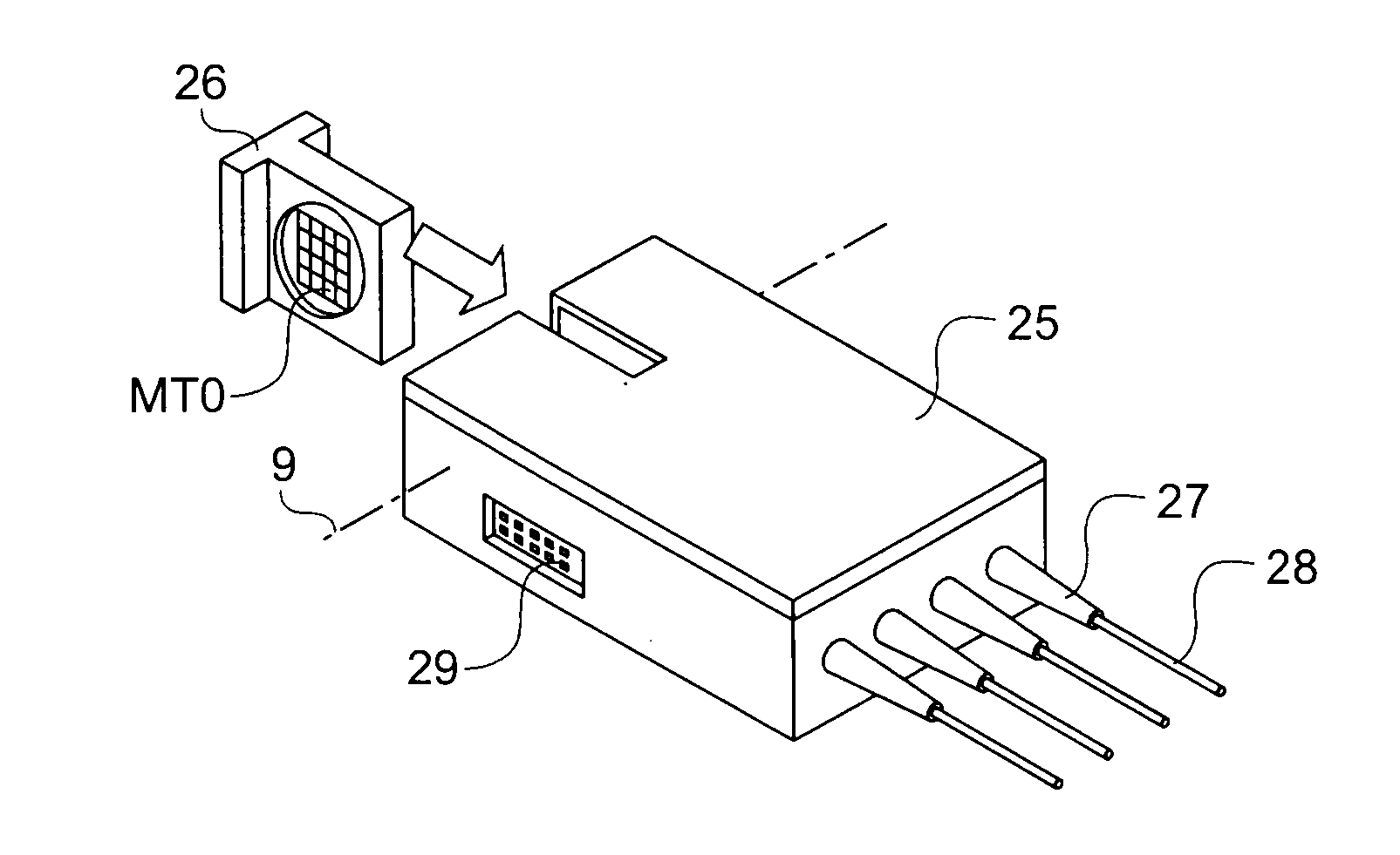
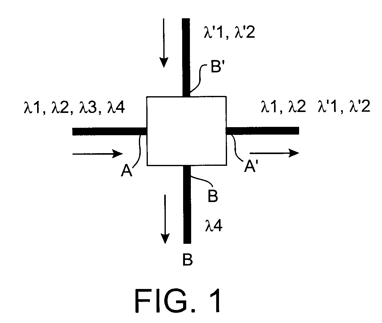
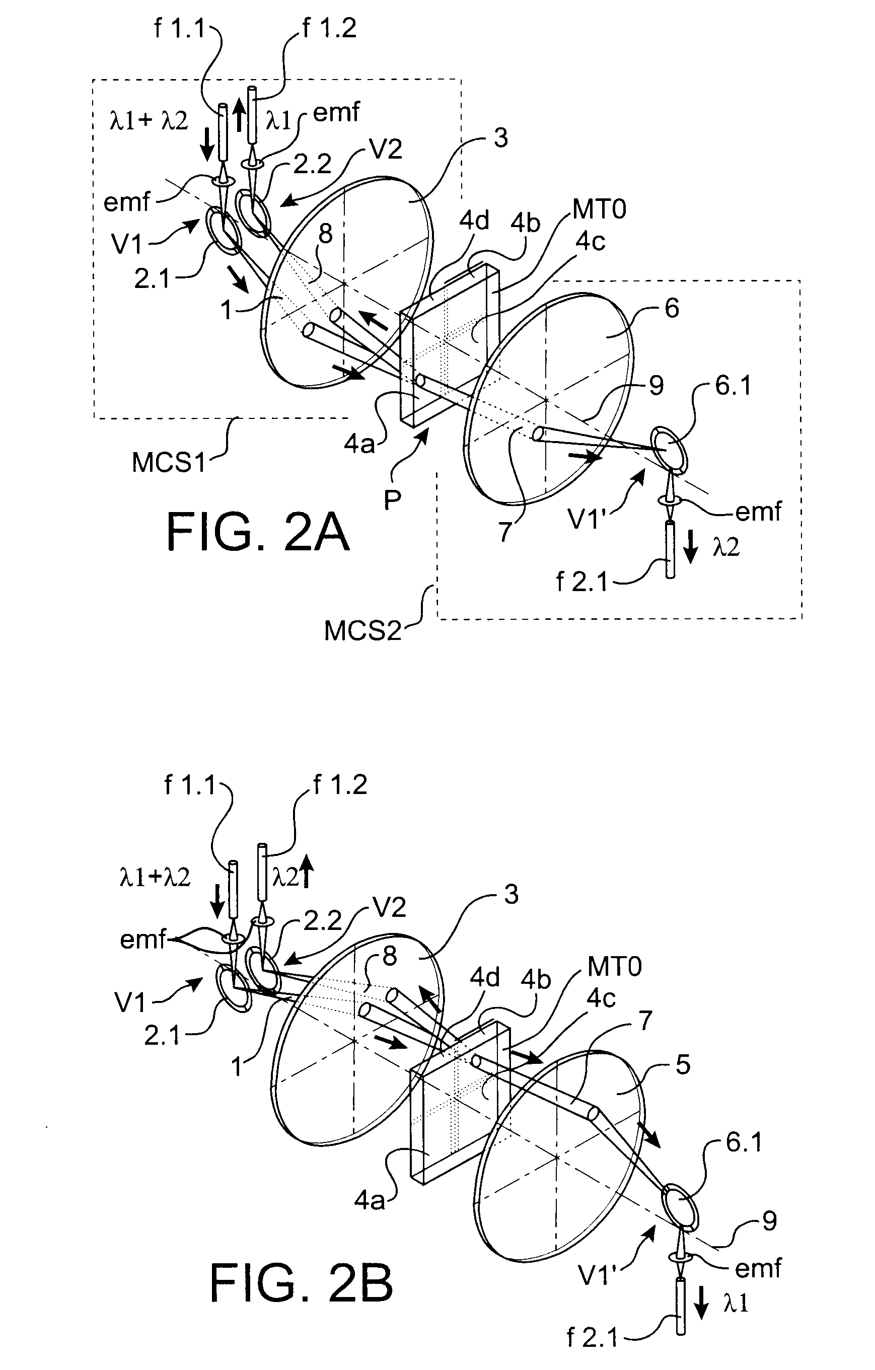
[0012]To attain these objectives, the invention more specifically concerns an optical processing device to process at least one main optical beam. It comprises a module which optically transforms or contributes towards optical transforming the main optical beam input into the processing device, this device consisting of a plurality of discrete elements arranged in one same plane. Upstream of the optical transforming module, or module contributing towards optical transformation, it also comprises an upstream spatial configuration module having an optical pathway through which the m...


PUM

PropertyMeasurementUnit
opticalaaaaaaaaaa
reflectionaaaaaaaaaa
transparentaaaaaaaaaa

Abstract

A device for optical processing of at least one main optical beam, including an optical transforming module contributing towards optical transformation of the main optical beam input in the processing device, formed of a plurality of discrete elements in one plane. An upstream spatial configuration module upstream of the optical transforming mode includes an optical pathway through which the main optical beam travels, this pathway includes one or more mobile optical deflection elements causing the main optical beam to take up potential spatial positions in the plane of the optical transforming module, these potential spatial positions coinciding with those of the discrete elements, the optical transforming module being static. Such a device may find application to telecommunications, chemistry, or biology.

Description

TECHNICAL AREA[0001]The present invention relates to a reconfigurable device for the processing of optical beams.[0002]The present invention particularly applies to optical communication systems in which the manufacturer endeavours to reduce manufacturing costs and the customer aspires for a system that has low consumption and is modular so that it is time-adaptive. This invention can be applied to other areas such as chemical or biological assays in which it is sought, as rapidly as possible and near-automatically, to evidence one or more substances contained in several samples of chemical or biological solutions.STATE OF THE PRIOR ART[0003]Subsequent to the bursting of the economic bubble in the telecommunications sector, operators are seeking to limit their installation and operating costs. They give priority to fibre-optic optical systems which are time-adaptive without requiring a full upgrade.[0004]These communications networks generally use wavelength multiplexing techniques....

Claims


Application Information

Patent Timeline
Patent Type & Authority Applications(United States)
IPC IPC(8): G01N21/00G02B26/00
CPCG02B6/2937G02B6/29395G02B6/2938
Inventor MARTINEZ, CHRISTOPHE
Owner COMMISSARIAT A LENERGIE ATOMIQUE ET AUX ENERGIES ALTERNATIVES
Why Eureka
Try Eureka