
Magnetic memory

a technology of magnetic memory and writing wire, which is applied in the field of magnetic memory, can solve the problems of increasing the amount of current flowing in the writing wire, increasing the cost of manufacturing an mram, and difficulty in achieving the effect of reducing the fluctuation of writing characteristics and reducing the writing curren

Inactive Publication Date: 2008-08-28
KK TOSHIBA
View PDF26 Cites 14 Cited by
  • Summary
  • Abstract
  • Description
  • Claims
  • Application Information

AI Technical Summary

Benefits of technology

The present invention provides a magnetic memory that reduces fluctuation in writing characteristic and allows reduction of writing current. The magnetic memory includes a magnetoresistance effect element with a magnetization pinned layer and a non-magnetic layer, and a first wiring layer that is electrically connected to the magnetoresistance effect element. The film face shape of the magnetoresistance effect element and the wiring film are positioned on the same plane, and the end face of the magnetoresistance effect element and the end face of the wiring film are positioned on the same plane. The magnetic memory also includes a storage layer with a magnetization pinned layer and a non-magnetic layer, and a writing wire that is provided on the opposite side of the magnetic recording layer from the non-magnetic layer. The magnetic memory can achieve high-speed writing and mass storage.

Problems solved by technology

However, magnetic field required for magnetization reversing, namely switching magnetic field becomes large according to fineness of the TMR element, which results in increase in amount of current flowing in the writing wire and, therefore, increase in power consumption.
However, it is difficult to manufacture an MRAM where a relative position between the end portion of the soft magnetic layer and the TMR element has been determined considering not only a deviation between the end portion of the soft magnetic layer and the TMR layer on a plane but also a deviation therebetween in a vertical direction which is a direction perpendicular to the plane.

Method used


Image

  • Magnetic memory
  • Magnetic memory
  • Magnetic memory

Examples


first embodiment

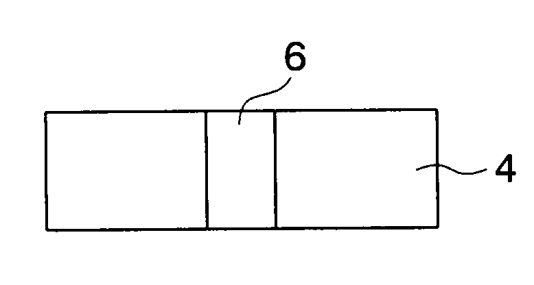
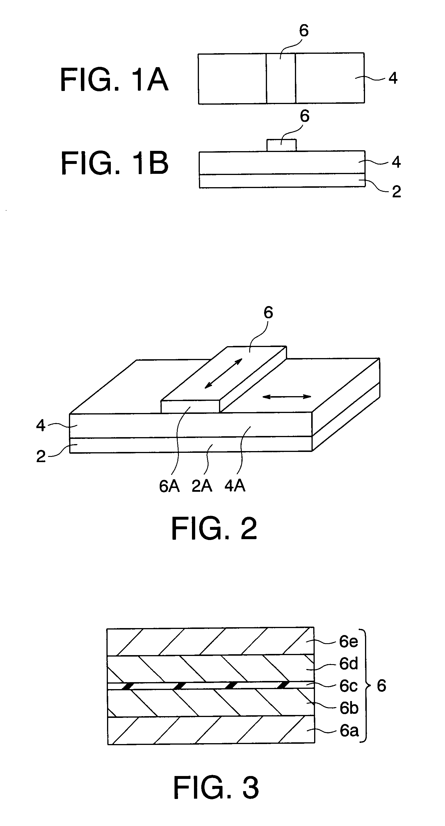
[0077]A magnetic memory according to a first embodiment of the present invention will be explained with reference to FIG. 1A to FIG. 11. A magnetic memory according to this embodiment has a plurality of memory cells arranged in a matrix array. A constitution of each memory cell is schematically shown in FIGS. 1A and 1B. FIGS. 1A and 1B are a plan view and a front view of a memory cell according to the embodiment, respectively. FIG. 2 is a perspective view of the memory cell according to the embodiment. The memory cell according to the embodiment is provided with a TMR element 6, a writing wire 4 for performing writing on the TMR element 6, and a yoke 2 formed of a magnetic layer. The writing wire 4 is formed on the yoke 2, and the TMR element 6 is formed on the writing wire 4. Incidentally, a wire (not shown) used for reading is provided on the TMR element 6.

[0078]As shown in FIG. 3, for example, the TMR element 6 has a stacking structure of a lower electrode layer 6a, a magnetizati...

second embodiment

[0103]Next, a constitution of a memory cell in a magnetic memory according to a second embodiment of the present invention is schematically shown in FIG. 12. The memory cell in the magnetic memory according to the embodiment is constituted such that, for example, a barrier metal layer 3 with a film thickness of 10 nm made of Ta has been inserted between the wire 4 connected to the TMR element 6 constituting the memory cell and the yoke 2 in the magnetic memory of the first embodiment. By inserting the barrier metal 3, mutual diffusion between material constituting a composition element for the wire 4, for example, Cu or Al, and material constituting the yoke 2, for example, permalloy (Ni—Fe) can be prevented from occurring. As the barrier metal, any one of TaN, TiN and WN can be used besides Ta. A barrier metal layer may be provided between the yoke 2 and a base substrate 100.

[0104]The magnetic memory of the embodiment can also reduce writing current without causing fluctuation of t...

third embodiment

[0105]Next, a constitution of a memory cell of a magnetic memory according to a third embodiment of the present invention is schematically shown in FIG. 13.

[0106]In the first and second embodiments, writing is performed by turning on two transistors to cause current to flow in only in the wire 4. At that time, magnetic field required for reversing magnetization of the magnetization free layer 6b of the TMR element 6 serves as a coercive force in a direction of an easy magnetization axis of the TMR element 6.

[0107]The third embodiment of the present invention has a constitution that another wire 14 is formed on the TMR element 6 so as to be perpendicular to the wire 4 (refer to FIG. 13). In this embodiment, writing can be performed utilizing asteroid characteristic of the TMR element 6 by causing current to flow in the wire 4 and the wire 14 simultaneously, and writing current is further reduced.

[0108]Next, a method for manufacturing the magnetic memory according to the embodiment wi...


PUM

PropertyMeasurementUnit
angleaaaaaaaaaa
angleaaaaaaaaaa
angleaaaaaaaaaa

Abstract

It is possible to reduce writing current without causing fluctuation of the writing characteristic. A magnetic memory includes: a magnetoresistance effect element having a magnetization pinned layer whose magnetization direction is pinned, a storage layer whose magnetization direction is changeable, and a non-magnetic layer provided between the magnetization pinned layer and the storage layer; and a first wiring layer which is electrically connected to the magnetoresistance effect element and extends in a direction substantially perpendicular to a direction of an easy magnetization axis of the storage layer, an end face of the magnetoresistance effect element substantially perpendicular to the direction of the easy magnetization axis of the storage layer and an end face of the first wiring layer substantially perpendicular to the direction of the easy magnetization axis being positioned on the same plane.

Description

CROSS-REFERENCE TO RELATED APPLICATION[0001]This application is a divisional of and claims the benefit of priority from U.S. Ser. No. 11 / 000,093 filed on Dec. 1, 2004, and is based upon and claims the benefit of priority from prior Japanese Patent Application No. 2003-402891, and 2004-244771 filed on Dec. 2, 2003, and Aug. 25, 2004 in Japan, the entire contents of each of which are incorporated herein by reference.FIELD OF THE INVENTION[0002]The present invention relates to a magnetic memory having a magnetoresistance effect element in a memory cell.RELATED ART[0003]A magnetic random access memory (MRAM) is a memory device which uses a magnetoresistance effect element in a cell portion which stores information or data, to which attention is paid as the next generation memory device characterized by high speed operation, mass storage, and nonvolatile. The magnetoresistance effect is a phenomenon where when magnetic field is applied to a ferromagnetic material, an electric resistance ...

Claims


Application Information

Patent Timeline
Patent Type & Authority Applications(United States)
IPC IPC(8): G11B5/33G11B5/39
CPCG11B5/39
Inventor AIKAWA, HISANORIUEDA, TOMOMASAKISHI, TATSUYAKAJIYAMA, TAKESHIASAO, YOSHIAKIYODA, HIROAKI
Owner KK TOSHIBA
Learn More