

Dsl System Estimation
a technology of digital communication system and system estimation, applied in the direction of transmission monitoring, frequency-division multiplex, instruments, etc., can solve the problems of many local loops not being suitable, bad splices or bad connectors, and the accuracy of some of the information is questionabl
- Summary
- Abstract
- Description
- Claims
- Application Information
AI Technical Summary
Benefits of technology
Problems solved by technology
Method used
Image

Examples
Embodiment Construction
[0027]The following detailed description of the invention will refer to one or more embodiments of the invention, but is not limited to such embodiments. Rather, the detailed description is intended only to be illustrative. Those skilled in the art will readily appreciate that the detailed description given herein with respect to the Figures is provided for explanatory purposes as the invention extends beyond these limited embodiments.
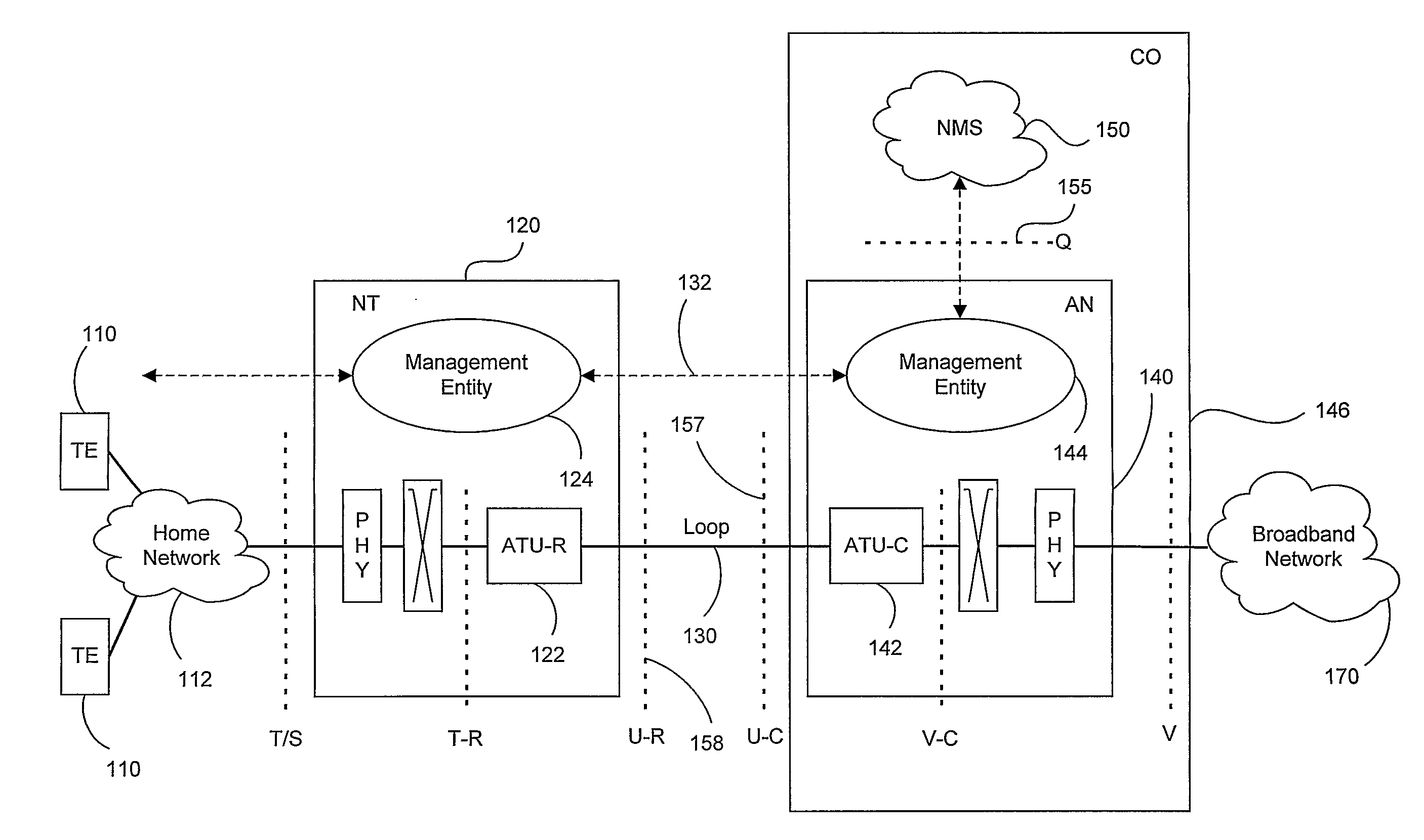
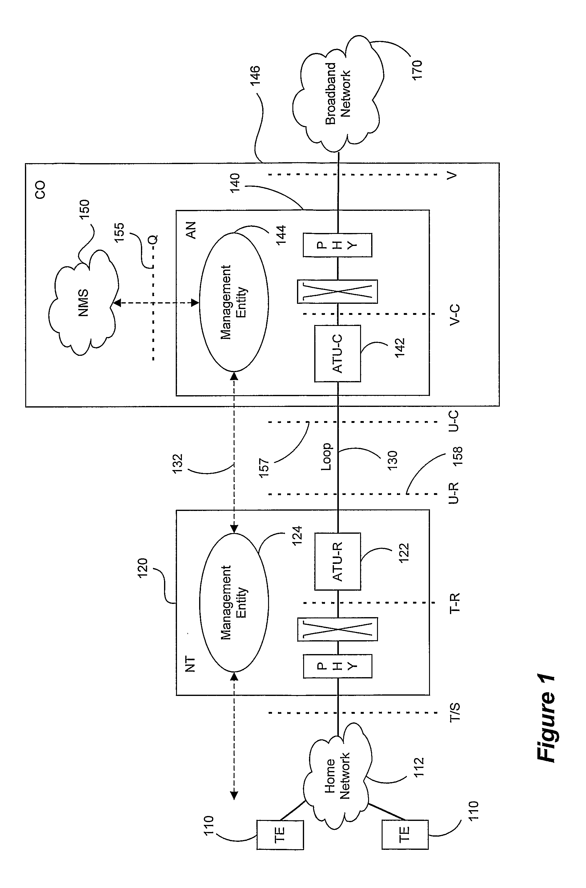
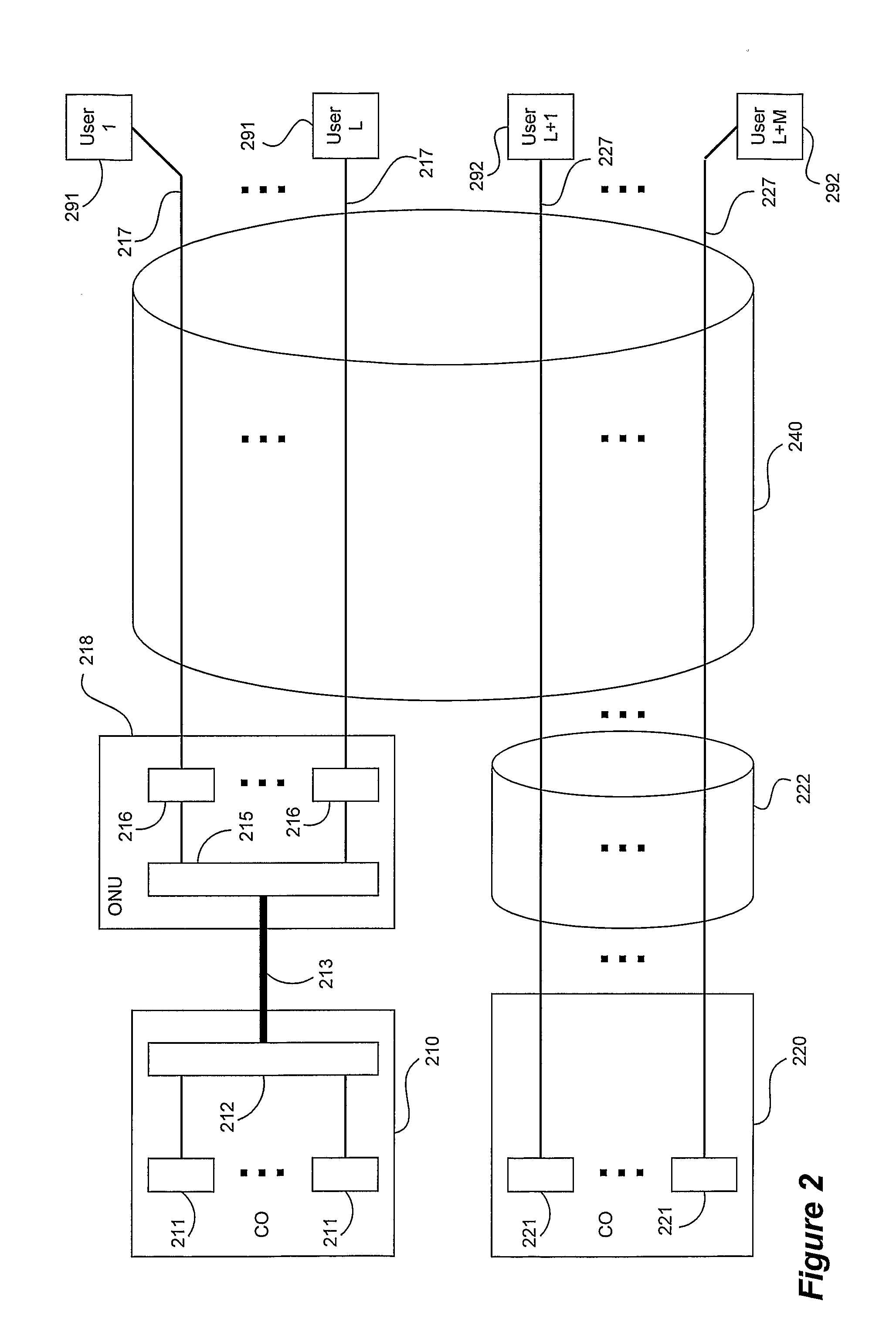
[0028]Embodiments of the present invention estimate the configuration of a given xDSL system (also equivalently referred to as a DSL system) based on operational data collected from a network element management system, protocol or the like. Using an estimate thusly generated, a controller then controls the operational mode (or may recommend a mode), for example by setting users' data rates, transmit power levels, etc. While the exact configuration of the DSL system may not be determinable, the whole or partial approximation or estimate obtained using t...
PUM
 Abstract
Description
Claims
Application Information