Device And Methods Of Providing Air Purification In Combination With Superficial Floor Cleaning

a technology of air purification and surface cleaning, applied in the direction of carpet cleaners, cleaning action control, heating types, etc., can solve the problems of clogging the device with pollutants, affecting the cleaning effect, and the location of the device is an issue, so as to reduce the mounting of particulates

Inactive Publication Date: 2008-08-28
SC JOHNSON & SON INC
View PDF99 Cites 66 Cited by
  • Summary
  • Abstract
  • Description
  • Claims
  • Application Information

AI Technical Summary

Benefits of technology

[0012]According to a further aspect of the present invention, the air purifying and surface cleaning mechanisms of the device can selectively operate in conjunction with one another to clean both the air and surfaces contacted by the device, but also to prevent the discharge of additional particulates from the surface into the air, thereby reducing the mount of particulates in the air that must be removed by the air purifier.
[0013]According to still another aspect of t

Problems solved by technology

Some of these indoor pollutants could also be contributing factors to frequent and unexplained headaches or sleepless nights that afflict numerous persons within the general population.
Often, the devices become clogged with pollutants, which requires disassembly of fan assemblies, replacement and/or repair of high voltage sources, extensive clearing of arrays of wires and electrodes that help create air movement, and replacement of filters that clog the devices unless they are cleaned.
These devices are often larger, noisier, more complicated, and more expensive than what some users may desire.
Often, the location of the device is an issue, as consumers want air cleaning in all rooms of the house.
Further, placement within a room is also problematic, as consumers often perceive that stationary air cleaners do not clean the entire airspace of a room and the air in corners of the room would remain stale.
However, even with air purifiers operating in a room, over time airborne contaminants settle upon surfaces.
These collections of dust, dander, pollen, and other co

Method used


Image

  • Device And Methods Of Providing Air Purification In Combination With Superficial Floor Cleaning
  • Device And Methods Of Providing Air Purification In Combination With Superficial Floor Cleaning
  • Device And Methods Of Providing Air Purification In Combination With Superficial Floor Cleaning

Examples


first embodiment

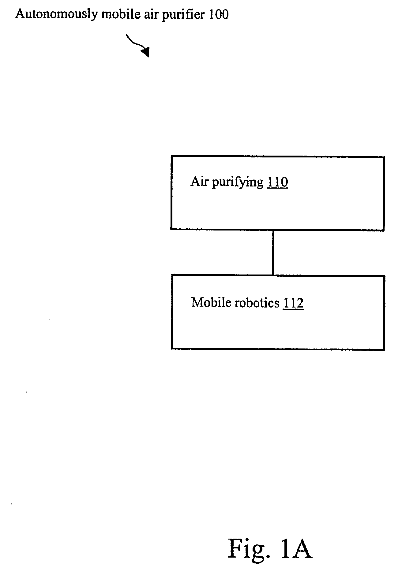
[0041]With reference now to the drawing figures in which like reference numerals designate like parts throughout the disclosure, FIG. 1A illustrates a functional block diagram of an autonomously mobile air purifier indicated generally at 100 that is constructed in accordance with the present invention. Autonomously mobile air purifier 100 includes the functional elements of an air purifying mechanism 110 and a mobile robotics mechanism 112.

[0042]Air purifying mechanism 110 describes the function of, for example, an air filter mechanism as is known in the art that draws in ambient air that contains contaminants, i.e. smoke, pollen, mold spores, animal dander, and other common particulate, and exhausts air with a reduced level of these impurities. Mobile robotics mechanism 112 provides the autonomous propulsion for autonomously mobile air purifier 100 that is well known to those skilled in the art. For example, mobile robotics mechanism 112 allows a variety of preprogrammed routes to ...

second embodiment

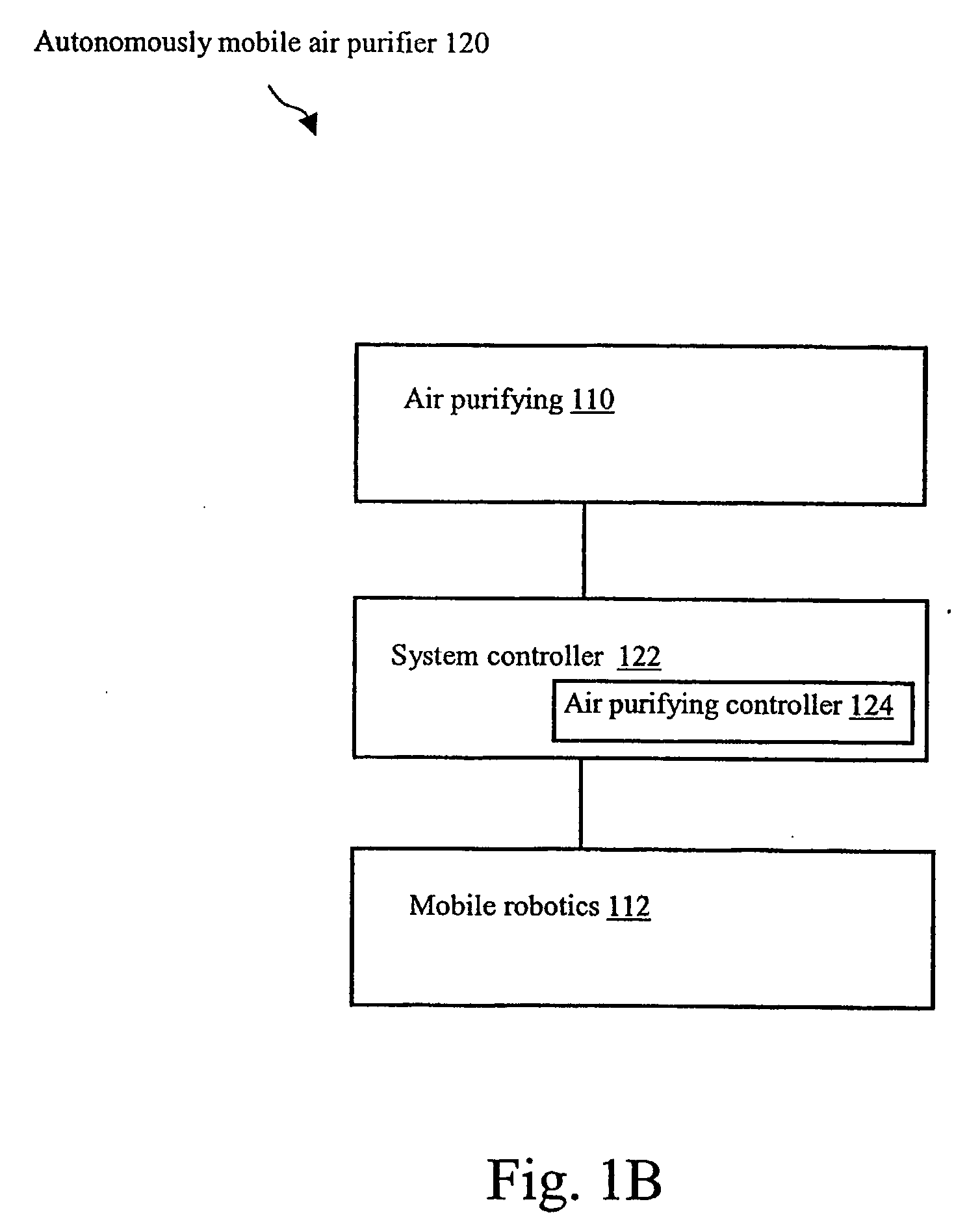
[0043]Referring to FIG. 1B, a functional block diagram is illustrated of an autonomously mobile air purifier 120 of a more complex configuration. Autonomously mobile air purifier 120 includes the functional elements of air purifying mechanism 110, mobile robotics mechanism 112, and a system controller 122, which further includes an air purifying controller 124.

[0044]System controller 122 describes a supervisory processing function that is capable of managing all of the operating functions of autonomously mobile air purifier 120. Air purifying controller 124 describes that function of system controller 122, which is capable of modifying its operation, based on any aspect of the operation of mobile robotics mechanism 112 or the functionality of air purifying mechanism 110. For example, air purifying controller 124 may adapt the air filtration rate of air purifier 120 in response to the speed of autonomously mobile air purifier 120 by monitoring a speed signal (not shown) from mobile r...

third embodiment

[0046]FIG. 1C illustrates a functional block diagram of an autonomously mobile air purifier 130 of a more preferred configuration. Specifically, in addition to including the functional elements of air purifying mechanism 110, mobile robotics mechanism 112, system controller 122, and air purifying controller 124, autonomously mobile air purifier 130 includes an air purifying sensing mechanism 132 and a particulate sensing mechanism 134.

[0047]Air purifying sensing mechanism 132 describes the function of monitoring the ability of air purifying mechanism 110 to remove particulates effectively, for example, monitoring the extent of use of an air filter (not shown) in mechanism 110 using suitable sensors (not shown) that are known in the art. Particulate sensing mechanism 134 describes the function of monitoring the degree of particulate concentration in the ambient air of autonomously mobile air purifier 130 by use of a particulate sensor that is well known by those skilled in the art, f...


PUM


Abstract

The present invention is a system for and method of providing an autonomously mobile air purifier and surface cleaner in combination with a source of air fragrance in a single device for home or office use. The autonomously mobile air and surface cleaner and fragrancing system includes an air purifier, a fragrancer, a floor cleaner, an input means, a power system, operational and auxiliary sensors, robotics that drive and steer the device, and a central controller operatively connected to each of the aforementioned items to control the operation of the device. The present invention also provides a method for the operation of the device using the air purifier, fragrancer, floor cleaner and robotics to clean a room, and for modifying the operation of the device in response to signals sent from the sensors or from the input means.

Description

CROSS-REFERENCE TO RELATED APPLICATION[0001]This application claims the benefit of U.S. Provisional Application Ser. No. 60 / 630,339, filed Nov. 23, 2004.FIELD OF THE INVENTION[0002]The present invention relates to autonomous and mobile cleaning devices. In particular, this invention relates to an autonomously mobile cleaning device that provides air purification or freshening, with an optional air fragrance feature, in combination with surface cleaning.BACKGROUND OF THE INVENTION[0003]The increase in awareness of the health risks inherent in air pollution recently has caused many people to reassess the quality of their indoor air and environment. Recent Environmental Protection Agency studies indicate that indoor air pollution levels could be 2-5 times higher than the ambient outdoor air pollution level. It is estimated by some that, on rare occasions, these indoor air pollution levels can be 100 times higher than outdoor air pollution levels. This is an increasingly important matte...

Claims


Application Information

Patent Timeline
IPC IPC(8): A47L11/40A61L9/04A61L9/12F24F8/10
CPCA47L11/24A47L11/4011A47L11/4047A47L11/4097A47L2201/00A61L9/04A47L2201/06A61L9/127F24F3/1603F24F2003/1689F24F2221/42A47L2201/022A61L9/122F24F8/50F24F8/10A61L9/12
Inventor CRAPSER, JAMES R.GASPER, THOMAS P.
Owner SC JOHNSON & SON INC
Why Eureka
Try Eureka