Eureka AIR delivers breakthrough ideas for toughest innovation challenges, trusted by R&D personnel around the world.

Method and System for a Multisystem Polar Transmitter

Inactive Publication Date: 2008-08-28
AVAGO TECH WIRELESS IP SINGAPORE PTE
View PDF11 Cites 6 Cited by
  • Summary
  • Abstract
  • Description
  • Claims
  • Application Information

AI Technical Summary

Benefits of technology

[0008]A method and/or system for a Multisystem Polar Transmitter, substantially as shown in and/or d

Problems solved by technology

In addition, the I and Q modulation approach may require good linearity of the power amplifier, often leading to power inefficient designs that suffer from parameter variability due to factors such as temperature.

Method used


Image

  • Method and System for a Multisystem Polar Transmitter
  • Method and System for a Multisystem Polar Transmitter
  • Method and System for a Multisystem Polar Transmitter

Examples


Embodiment Construction

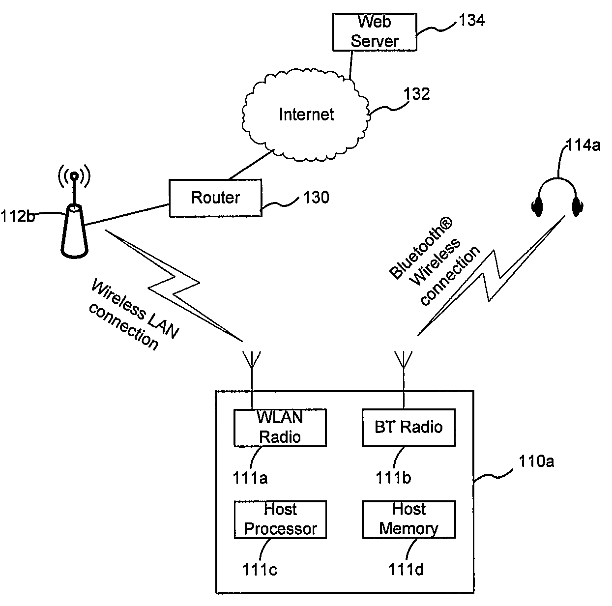
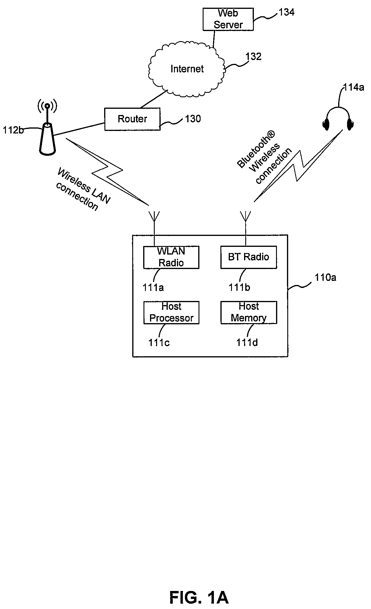
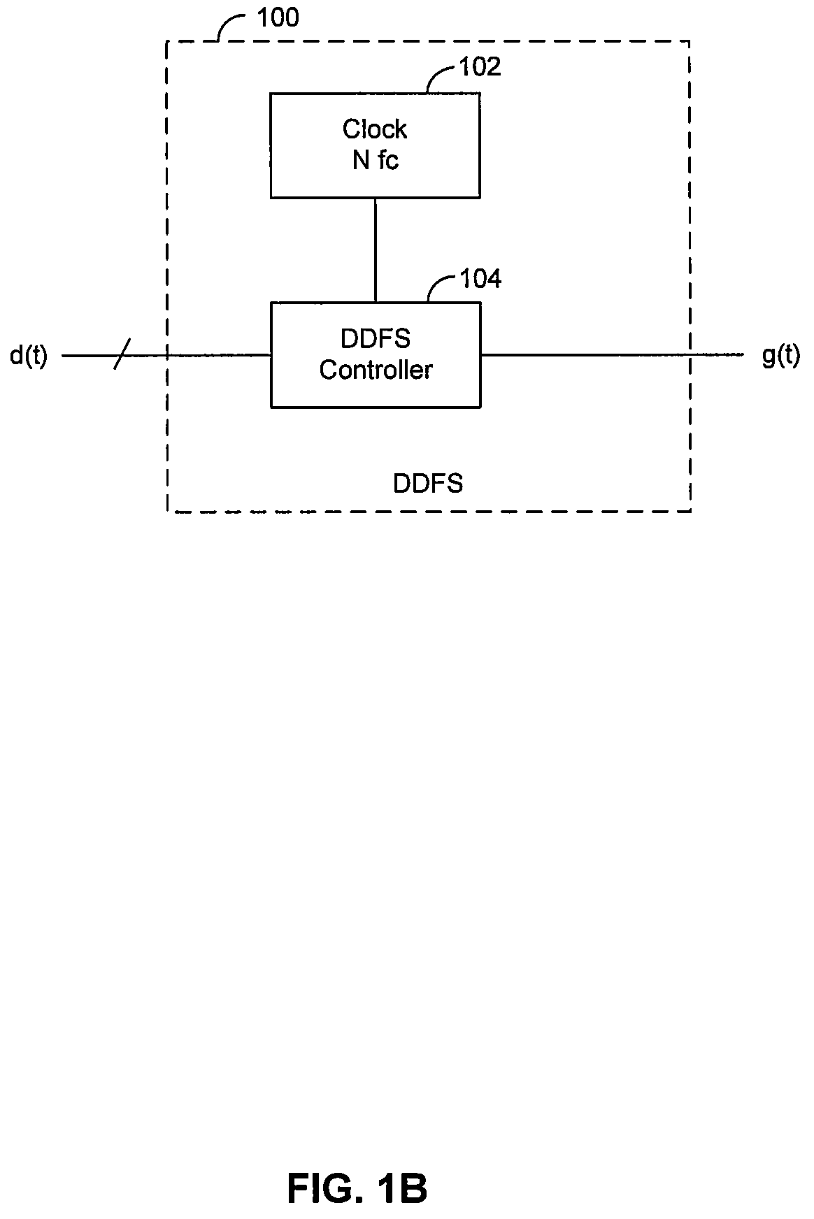
[0014]Certain embodiments of the invention may be found in a method and system for a Multisystem Polar Transmitter. Aspects of a method and system for a Multisystem Polar Transmitter may include in a single integrated circuit comprising one or more Direct Digital Frequency Synthesizer (DDFS) and one or more circuits that processes one or more signals compliant with at least a first wireless protocol and a second wireless protocol for transmission, may generate a plurality of signals compliant with at least the first wireless protocol and the second wireless protocol, wherein at least one of the signals is polar modulated using the DDFS. One or more circuits may comprise a plurality of wireless transmitters. The plurality of wireless transmitters may comprise a Bluetooth® transmitter and a Wireless LAN transmitter. In another embodiment of the invention, a plurality of baseband signals compliant with the first and second protocol, respectively, may be combined. The first protocol may...


PUM


Abstract

Aspects of a method and system for a Multisystem Polar Transmitter may include a single integrated circuit comprising one or more Direct Digital Frequency Synthesizer (DDFS). The single integrated circuit may generate a plurality of signals compliant with at least a first wireless protocol and a second wireless protocol. At least one of the plurality of signals is polar modulated using the DDFS. The single integrated circuit may comprise a plurality of wireless transmitters. In another embodiment of the invention, a plurality of baseband signals compliant with the first and second protocols may be combined. The first protocol may be Bluetooth® and the second protocol may be Wireless LAN. The combined plurality of baseband signals may be modulated via a single wireless transmitter on the integrated circuit. The phase and frequency for polar modulation may be adjusted using the DDFS, while the amplitude may be adjusted using an amplifier.

Description

CROSS-REFERENCE TO RELATED APPLICATIONS / INCORPORATION BY REFERENCE[0001]This application makes reference to:U.S. application Ser. No. ______ (Attorney Docket No. 18195US01), filed on even date herewith;U.S. application Ser. No. ______ (Attorney Docket No. 18201US01), filed on even date herewith;U.S. application Ser. No. ______ (Attorney Docket No. 18202US01), filed on even date herewith;U.S. application Ser. No. ______ (Attorney Docket No. 18203US01), filed on even date herewith;U.S. application Ser. No. ______ (Attorney Docket No. 18204US01), filed on even date herewith; andU.S. application Ser. No. ______ (Attorney Docket No. 18205US01), filed on even date herewith.[0002]Each of the above referenced applications is hereby incorporated herein by reference in its entirety.FIELD OF THE INVENTION[0003]Certain embodiments of the invention relate to signal processing for communication systems. More specifically, certain embodiments of the invention relate to a method and system for a Mu...

Claims


Application Information

Patent Timeline
IPC IPC(8): H04B1/02
CPCH04B1/406
Inventor ROFOUGARAN, AHMADREZA
Owner AVAGO TECH WIRELESS IP SINGAPORE PTE
Why Eureka
Eureka Blog
Learn More