
Composite doors

a technology of composite doors and doors, applied in the field of composite doors, can solve the problems of time-consuming and difficult procedures, differential weathering patterns, and inconvenient achieve the effects of convenient production of relatively complex shapes, precise shapes and dimensions, and economics

Inactive Publication Date: 2008-09-04
LSSD UK
View PDF10 Cites 22 Cited by
  • Summary
  • Abstract
  • Description
  • Claims
  • Application Information

AI Technical Summary

Benefits of technology

[0008]Very conveniently, the door skins are moulded, and the one or more bosses are in the form of mouldings. Preferably, the door skins are moulded from sheet moulding compound (SMC). It has been found that SMC door skins have a strength which is particularly well suited to the present invention, enabling hardware fixings to be attached in place reliably.
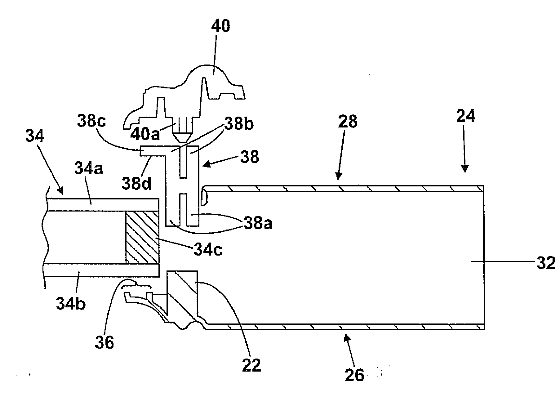
[0014]Advantageously, the at least one glazing panel retention means is moulded. Conveniently, the at least one glazing panel retention means is injection moulded. Moulded glazing panel retention means are economical to produce and also have the advantages that it is possible to manufacture a precisely defined shape of precisely defined dimensions. Additionally, it is convenient to produce relatively complex shapes. This can be contrasted with prior art glazing panel retention means fabricated from materials such as timber and metal, which require complex machining or processing in order to achieve precise shapes and dimensions.
[0015]Advantageously, the composite door further includes a trim which is coupled to the glazing panel retention means in the vicinity of the second door skin. An advantage associated with the present invention is that the trim can be positioned to be substantially flush with the exterior surface of the second door skin.
[0019]Advantageously, at least one of the first and second door skins have one or more grooves formed therein for receiving a glazing panel sealant, thereby enabling the glazing panel to be sealed against at least one of the door skins.

Problems solved by technology

This procedure is time consuming and somewhat difficult to perform.
Additionally, the end result is not aesthetically pleasing.
Further problems associated with cassette systems are that they are typically expensive, relatively insecure, and, since they may be constructed of different materials to the outer surface of the door, can result in differential patterns of weathering.
Internal glazing reinforcement mechanisms which are positioned between the door skins of a composite door are known, but the mechanisms can be costly, necessitate the use of relatively small glazing panels, and can be time consuming to construct.

Method used


Image

  • Composite doors
  • Composite doors
  • Composite doors

Examples


Embodiment Construction

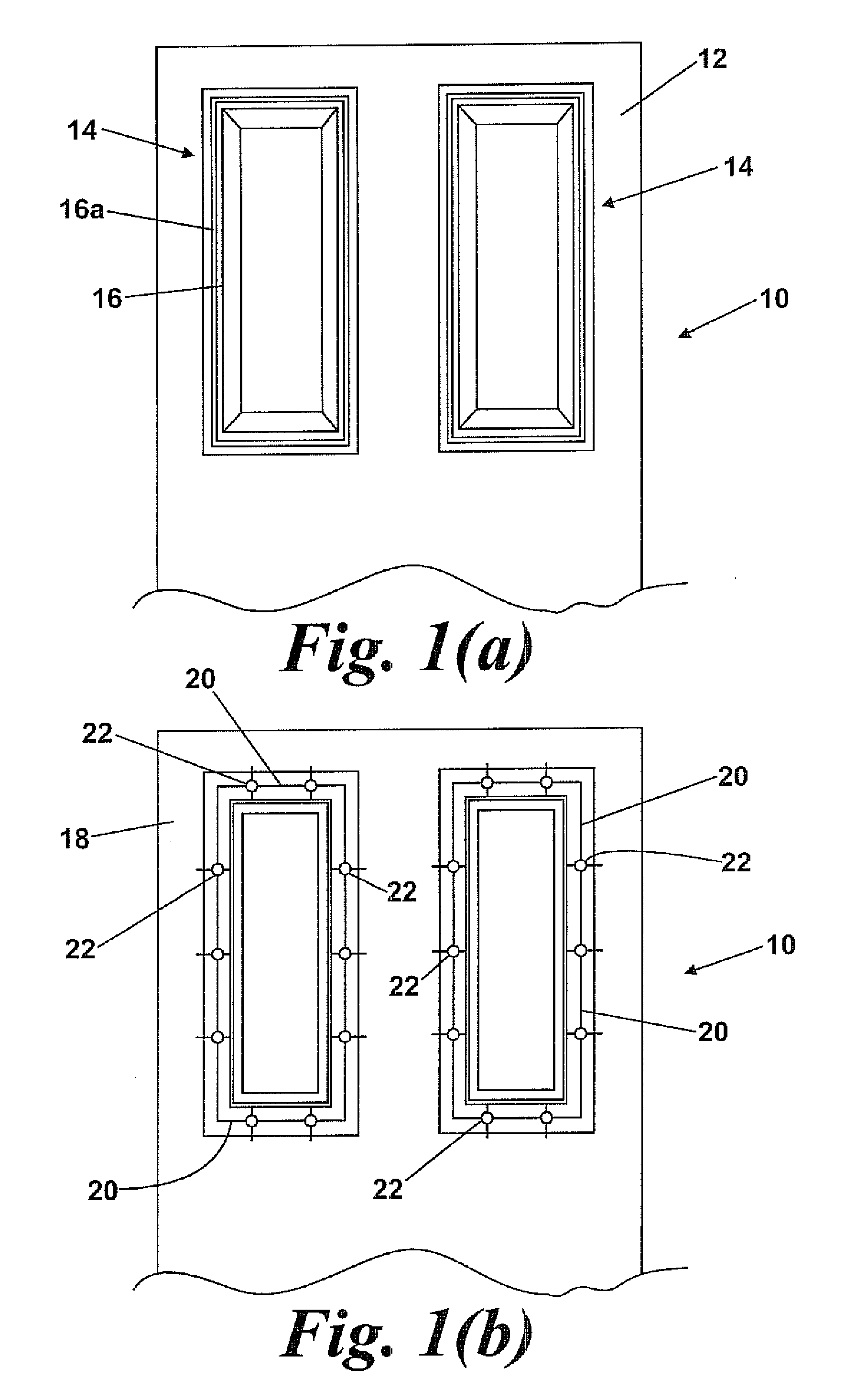
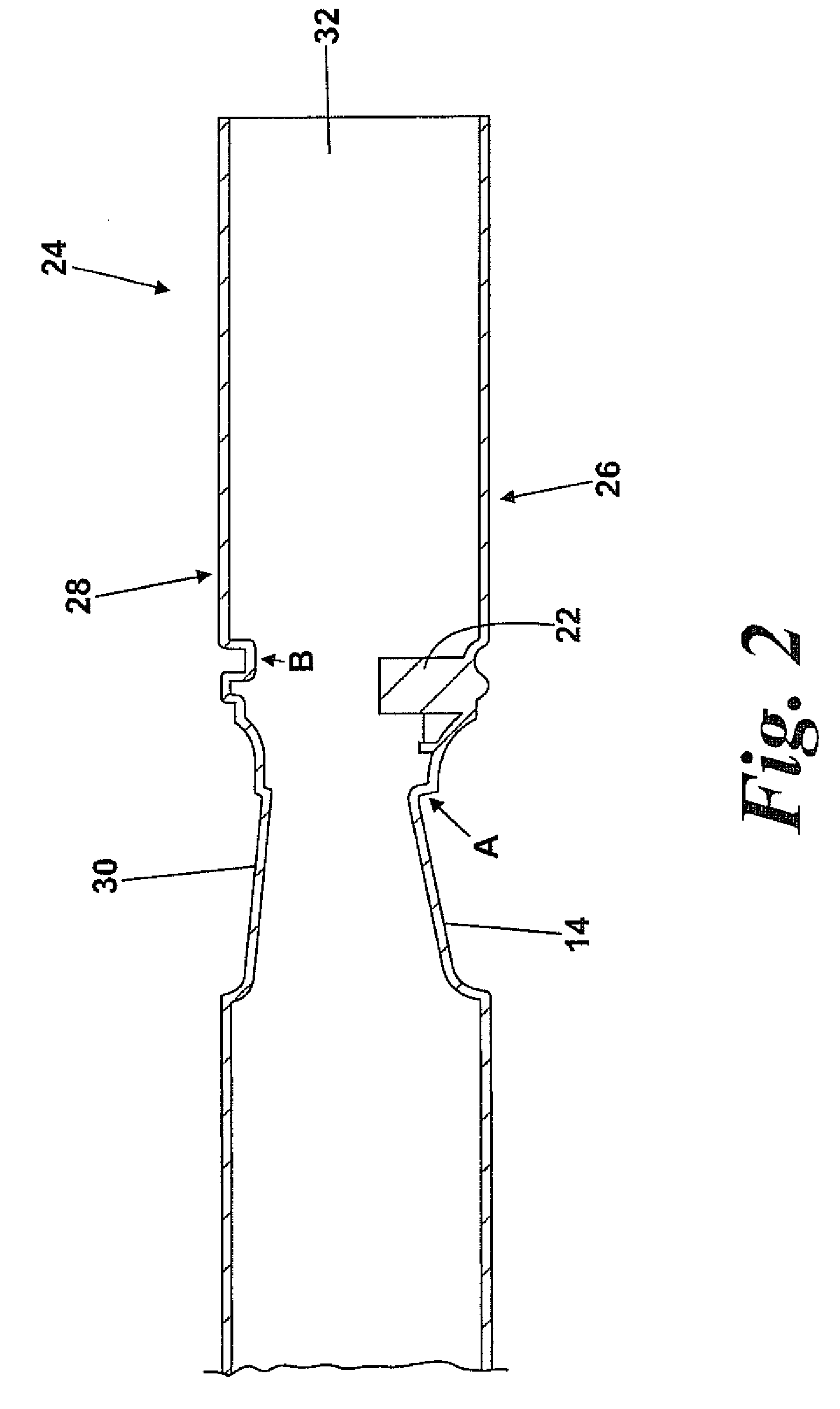
[0049]FIG. 1 shows a door skin 10 having on its exterior surface 12 panels 14 comprising concentric lip portions 16 as is well known in the art. As shown in FIG. 1(b) the interior surface 18 of the door skin 10 comprises a number of ribs 20 having a plurality of bosses 22 formed thereon. The ribs are in registry with the outer lip 16a of the panels 14. FIG. 2 shows a composite door 24 comprising a first door skin 26 which is generally of the type shown in FIG. 1, and shares many common features; identical numerals are used to denote such shared features. The composite door 24 further comprises a second door skin 28 which has panels 30 which are in registry with the panels 14 of the first door skin 26. The door skins 26, 28 are separated by a foam core 32, and are mounted on a door frame (not shown) in the conventional manner.

[0050]The composite door 24 shown in FIG. 2 is unglazed, but offers the facility for a glazing panel to be installed conveniently, quickly, and with an aestheti...


PUM

PropertyMeasurementUnit
timeaaaaaaaaaa
strengthaaaaaaaaaa
shapeaaaaaaaaaa

Abstract

According to the invention there is provided a composite door including a first and a second door skin, each door skin having an interior and an exterior surface, in which the interior surface of at least the first door skin has one or more bosses formed therein for receiving a fastening element.

Description

[0001]This application claims the benefit of U.S. Provisional Patent Application Ser. No. 60 / 893,172, filed Mar. 6, 2007, and United Kingdom Application No. 0704181.7, filed Mar. 3, 2007, the disclosures of each of which are incorporated herein in their entirety by reference.FIELD OF THE INVENTION[0002]This invention relates to composite doors, glazing panel retention means and door skins.BACKGROUND OF THE INVENTION[0003]Composite doors are doors having main bodies which are formed from more than one material, and can be contrasted with traditional doors such as timber doors. One example of a composite door is the type that utilises a pair of plastic door skins, such as is taught in GB 2267529. The door skins are mounted on a frame and panels of a suitable material are located within the frame between the door skins. It is also known to produce composite doors in a single moulding process.[0004]It is commonly desired to provide doors having glazing apertures in which a glass panel o...

Claims


Application Information

Patent Timeline
Patent Type & Authority Applications(United States)
IPC IPC(8): E06B3/20
CPCE06B3/5892E06B2003/7023E06B3/78
Inventor HODGES, DAVID KENNETHCONROY, VINCENT
Owner LSSD UK
Learn More