Cleaning Method and Apparatus

a cleaning method and cleaning apparatus technology, applied in the field of cleaning methods and systems, can solve the problems of still a considerable amount of water used, relatively large amount of water to be used, and relatively large cost, and achieve the effect of improving cleaning methods and cleaning apparatus

Active Publication Date: 2008-09-04
LAUZON NORMAND
View PDF13 Cites 40 Cited by
  • Summary
  • Abstract
  • Description
  • Claims
  • Application Information

AI Technical Summary

Benefits of technology

[0026]An object of the present invention is therefore to provide an improved cleaning method and an improved cleaning apparatus.

Problems solved by technology

Furthermore, piping systems, associated vessels and associated apparatuses may also require cleaning to permit maintenance thereon and, in some cases, subsequently to such maintenance.
There is still a considerable amount of water used.
A large amount of water is used to push the product being cleaned out of the circuitry.
In other words, between each phase, water is used to eliminate food product or washing product residues, which also causes a relatively large amount of water to be used.
In addition, in some cases the returning water and residues needs to be treated before being released, which results in relatively large costs due to the relatively large quantity of returning water and residues to process.
For example, incorporating air into the product may result in oxidizing the final product and, hence, altering its taste and its expected lifetime.
Also, incorporation of air in the product may result in the production of foam, which may render the process inaccurate.
Accordingly, there is a loss of product since the air is often unable to push all of the product downstream, particularly in situations wherein there are changes in piping diameter and wherein there exists vertical piping in certain areas, which is often the case.
However, that principle is rarely seen because of the following drawbacks:i. the recovery device can become stuck in the pipe, which sometimes even require that the pipe be cut for recovery of the recovery device;ii. to identify where the recovery device may become stuck, the recovery device typically contains a magnet and, outside the pipe, magnet detectors are installed along the pipe, this results in a relatively expensive cleaning system;iii. the recovery device is practically only usable in pipes of substantially constant diameter with no protruding val
ve. As soon as the circuitry has valves, plates, pumps, filters or any other process equipment, this principle can't be used; andiv. curved pipes need to have relatively large radius of curvature, which is relatively expensive and can present a problem of space in the plant.
However, in this method the granules complicate an eventual recovery of food residues that are washed using this fifth principle.
Furthermore, this principle cannot typically be used to clean processing equipment in which vessels are equipped with spray devices because the granules may plug the vessel spray device, or they can settle at the bottom of the vessel and be relatively hard to dislodge.
Also, systems using this principle are relatively complex and therefore relatively expensive and relatively more prone to malfunction than systems wherein only a fluid is used.

Method used


Image

  • Cleaning Method and Apparatus
  • Cleaning Method and Apparatus
  • Cleaning Method and Apparatus

Examples


Embodiment Construction

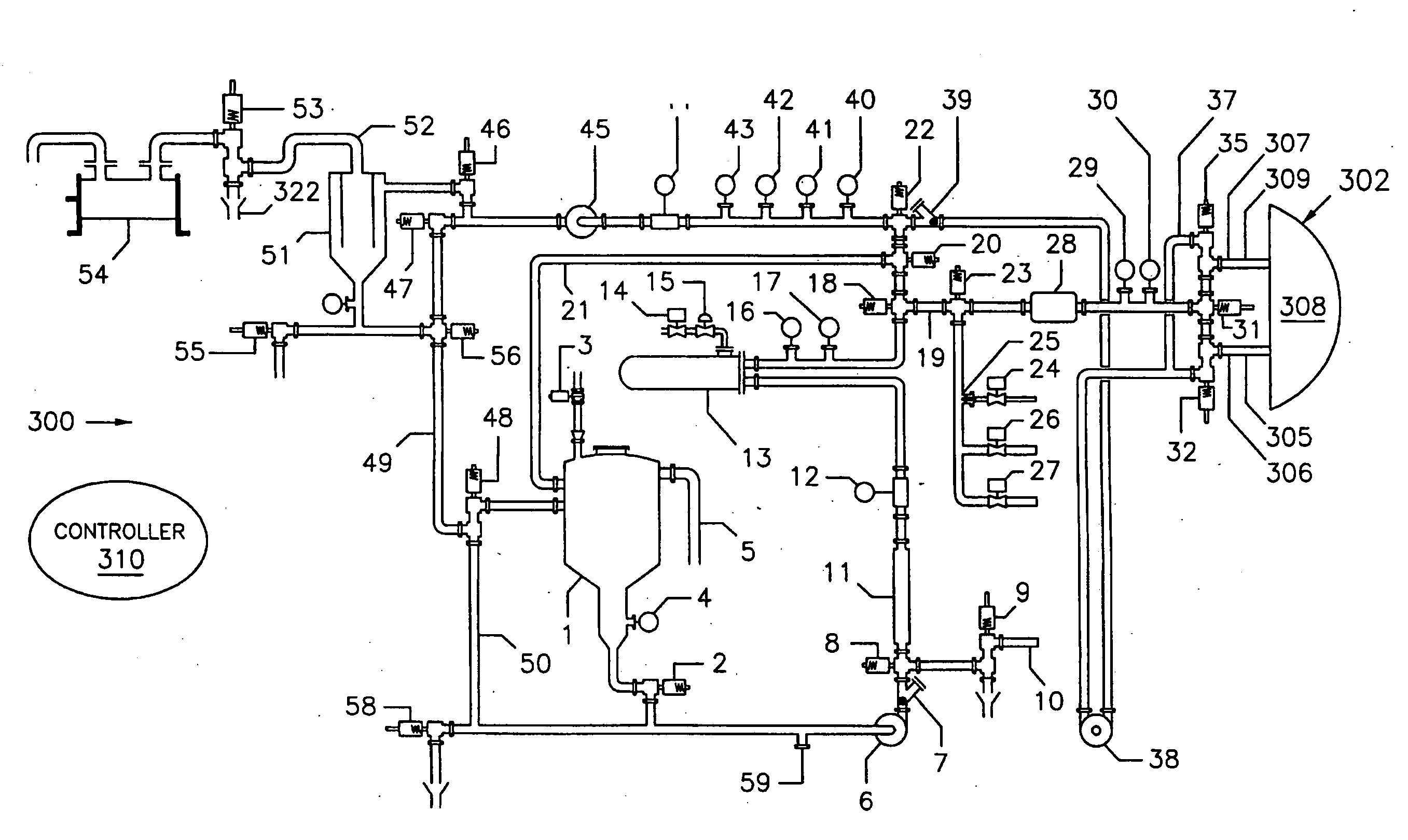
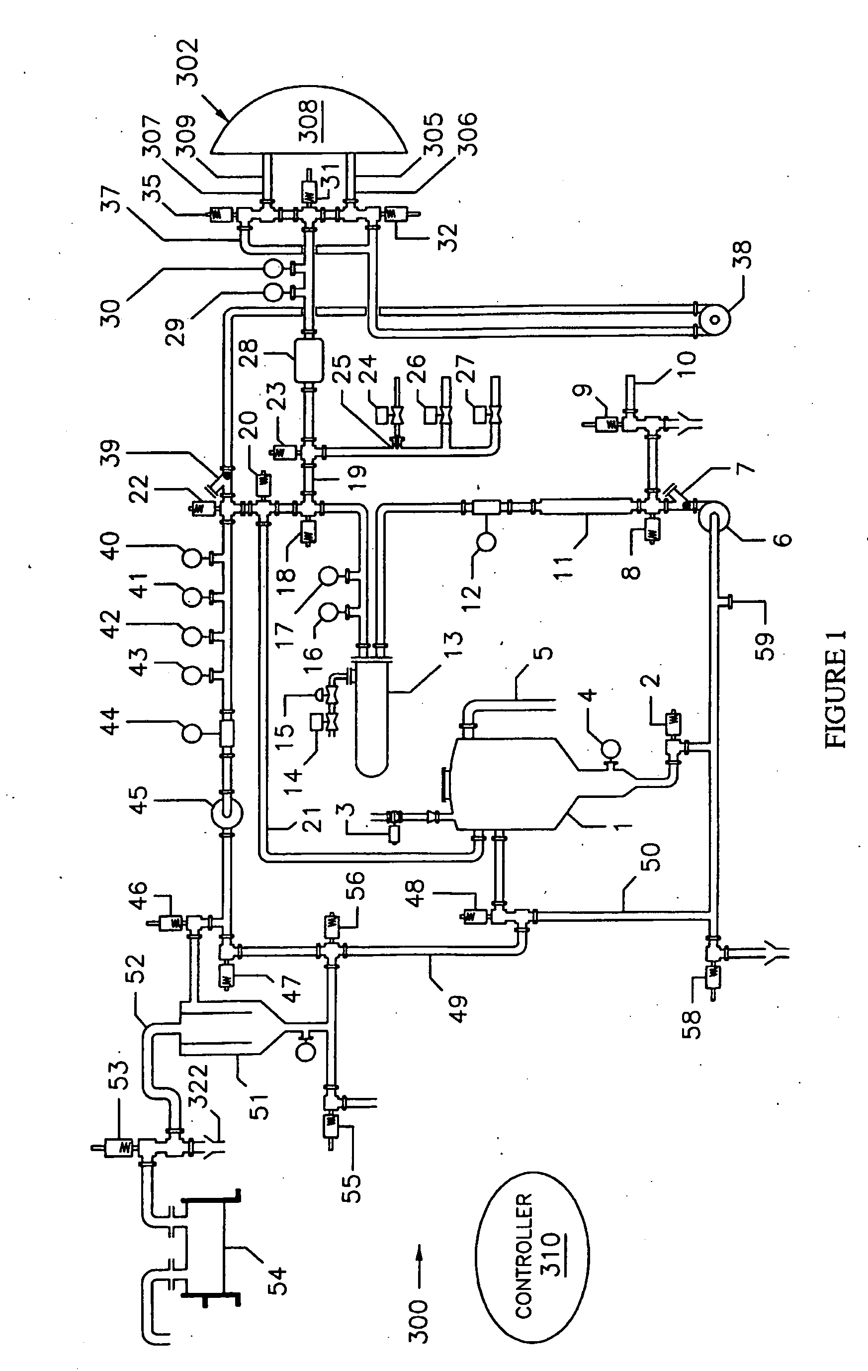
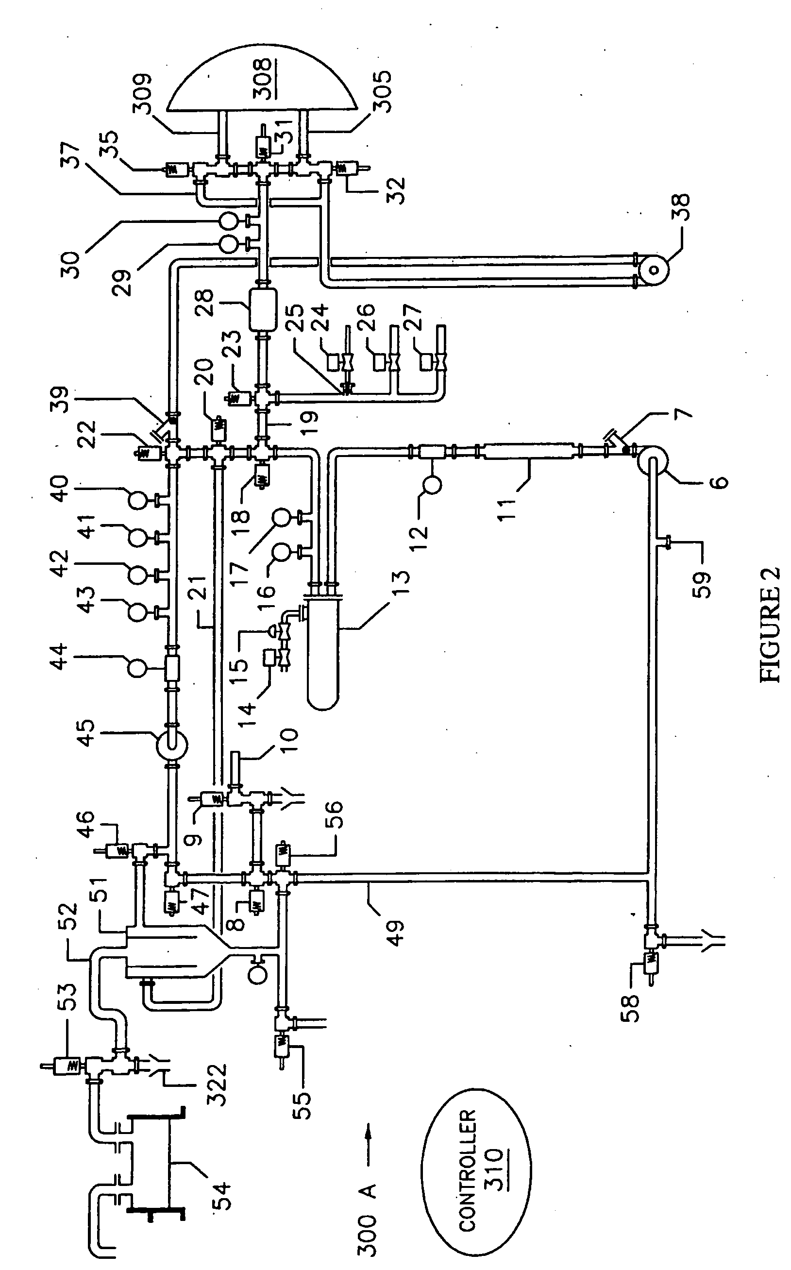
[0068]The following description often refers to specific types of vessels, such as reservoirs, tanks and silos, among others. The reader skilled in the art will readily appreciate that the use of a specific type of vessel is made for illustration purposes and that in any case wherein a specific type of vessel is mentioned, it is within the scope of the invention to use also any other suitable type of vessel.

[0069]FIG. 1 illustrates in a schematic view an apparatus 300 for cleaning an interior surface of a processing equipment, referred to generally by the reference numeral 302. The apparatus 300 is a so-called clean-in-place apparatus that is permanently, or semi-permanently connected to the processing equipment 302. However, the reader skilled in the art will readily appreciate that the claimed invention is also applicable to apparatuses that are non-permanently connected to a processing equipment to dean.

[0070]The processing equipment 302 includes a first pipe section 305 defining...


PUM

PropertyMeasurementUnit
internal pressureaaaaaaaaaa
volumeaaaaaaaaaa
pressureaaaaaaaaaa

Abstract

A method for cleaning an interior surface of a processing equipment using a treatment liquid, the processing equipment including a pipe section defining pipe section first and second ends, the pipe section defining a pipe section volume delimited by the pipe section first and second ends, the pipe section being initially at an initial internal pressure. The method includes introducing a predetermined volume of the treatment liquid, the predetermined volume being substantially smaller than the pipe section volume circulating the predetermined volume of the treatment liquid through the pipe section by simultaneously reducing an internal pressure within the pipe section at a location substantially adjacent the pipe section second end and increasing an internal pressure within the pipe section at a location substantially adjacent the pipe section first end.

Description

FIELD OF THE INVENTION[0001]The present invention relates to the general field of cleaning method and systems and is particularly concerned with a cleaning method and apparatus for use with piping systems and associated equipments.BACKGROUND OF THE INVENTION[0002]Piping systems, vessels and associated apparatuses are used extensively in many industrial applications wherein fluids and other substances are used, produced or transformed. In certain industries, such as for example pharmaceutical industries and food processing industries, including non-limitatively the dairy industry, cleanliness is of utmost importance and is governed by strict regulatory requirements and standards.[0003]Accordingly, the cleaning of corresponding piping systems, vessels and associated apparatuses must be performed regularly or daily to maintain sanitary standards and to meet strict regulatory requirements. Furthermore, piping systems, associated vessels and associated apparatuses may also require cleani...

Claims


Application Information

Patent Timeline
Patent Type & Authority Applications(United States)
IPC IPC(8): B08B9/032B08B3/08B08B13/00B05B13/06A47J31/60A61L2/18A61L2/22A61L2/24B08B9/02B08B9/08B08B9/093
CPCA47J31/60A61L2/18A61L2/22B08B9/08B08B9/032B08B9/0321B08B9/0325A61L2/24
Inventor LAUZON, NORMAND
Owner LAUZON NORMAND
Why Eureka
Try Eureka