Column current source

a current source and column technology, applied in the field of column current sources for image sensors, can solve the problems of inherent lag associated with powering up and down the array, and achieve the effect of reducing the circuit siz

Active Publication Date: 2008-09-04
STMICROELECTRONICS RES & DEV
View PDF3 Cites 13 Cited by
  • Summary
  • Abstract
  • Description
  • Claims
  • Application Information

AI Technical Summary

Benefits of technology

[0016]The size of the circuit can be reduced by only using one resistive element common to each column current source. For example, a resistive e

Problems solved by technology

When switching between values of ICOLBIAS there is an inherent lag associated with powe

Method used


Image

  • Column current source
  • Column current source
  • Column current source

Examples


Embodiment Construction

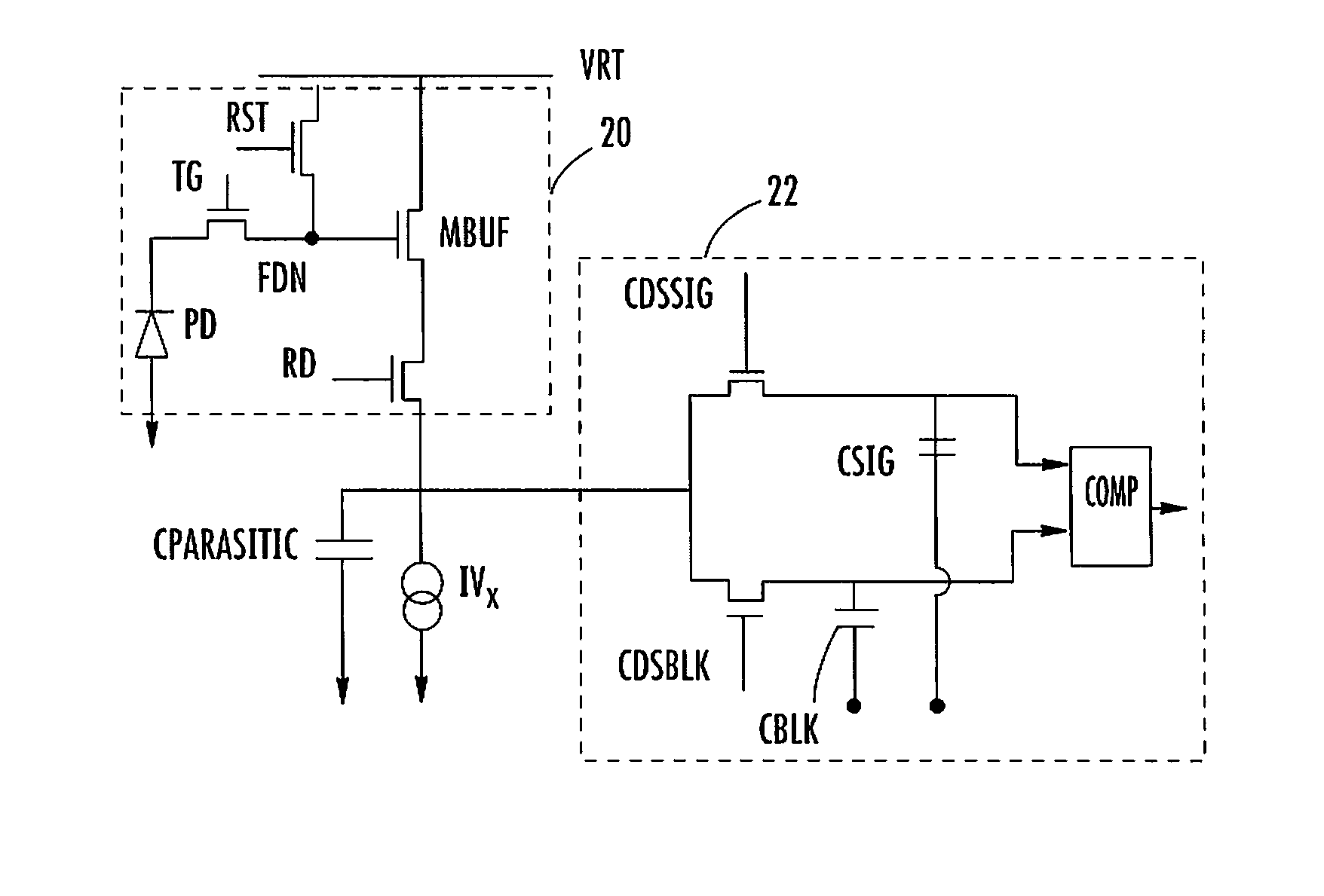
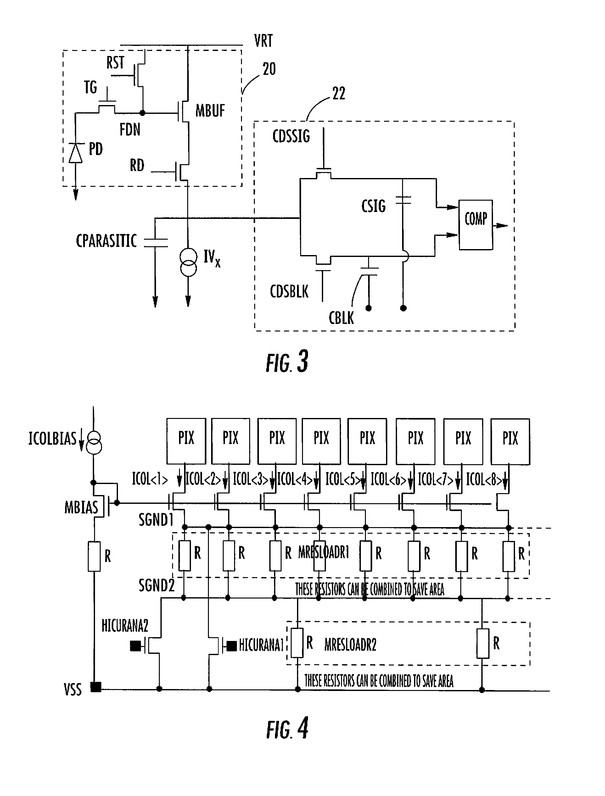
[0025]Referring to FIG. 3, a pixel 20 is shown having a photodiode PD, a reset transistor RST, a transfer gate transistor TG, a read transistor RD and a pixel buffer transistor (MBUF), which acts as a source follower. The pixel 20 is part of a pixel array (not shown) and resides in a column of pixels of the pixel array connected in a similar manner between a voltage supply VRT and a column current source lVx. Each column has an associated parasitic capacitance Cparasitic and a readout circuit 22. The readout circuit 22, in this example, comprises a correlated double sample (CDS) arrangement having a signal sample capacitor CSIG, a reset sample capacitor CBLK, a CDS signal transistor CDSSIG, a CDS reset transistor CDSBLK, a comparator COMP. The signal from the comparator COMP would then be available for the remainder of the output circuitry in a known manner.

[0026]Referring now to FIG. 4, a pixel array having columns of pixels PIX is shown. Only one pixel is shown in each column, but...


PUM


Abstract

A column current source for an image sensor includes an array of pixels arranged in rows and columns, a reference current source, a transistor connected as a source follower to the reference current source and forming one half of a current mirror, and a plurality of current sources each connected to a column of pixels and with each current source forming the other half of the current mirror, thereby mirroring the reference current source. The current sources are connected to a first common node. A resistor is connected between the first common node and a second common node. One or more resistors are connected in series between the second common node and the transistor drain, and two or more switches are selectively operable to short circuit the resistors allowing the current sources to provide more than two current levels, thereby optimizing the image sensor current consumption for mobile devices.

Description

FIELD OF THE INVENTION[0001]The present invention relates to a column current source for an image sensor, and, in particular, but not exclusively, for reducing or minimizing the current usage of a column current source for an image sensor.BACKGROUND OF THE INVENTION[0002]Image sensors traditionally are made up of an array of light sensitive pixels. The image sensor read-out the value of each pixel to produce an image. Before the array of pixels is exposed to receive light, each pixel is reset. As shown in prior art FIG. 1, a current column source ICOL is provided for each column to bias the pixels PIX of that column and, as such, reset their values.[0003]Each column current source ICOL is one half of a current mirror circuit. A diode-connected transistor MPIAS makes up the other half of the current mirror and is common to each column current source ICOL. The current ICOLBIAS is mirrored at ICOL<1> to ICOL. The current column source ICOL is not required continuously during an i...

Claims


Application Information

Patent Timeline
IPC IPC(8): G09G3/10H04N5/335
CPCH04N5/23241H04N5/378H04N5/335H04N23/651H04N25/00H04N25/75
Inventor PURCELL, MATTHEW
Owner STMICROELECTRONICS RES & DEV
Why Eureka
Try Eureka