Free-standing turbine blade

a free-standing turbine blade technology, applied in the direction of liquid fuel engines, vessel construction, marine propulsion, etc., can solve the problems of additional vibrational resonance modes of blades, unwanted humming of diffusers, unwanted mechanical loading of blades, etc., and achieve the effect of low gap losses

Inactive Publication Date: 2008-09-04
SIEMENS AG
View PDF12 Cites 44 Cited by
  • Summary
  • Abstract
  • Description
  • Claims
  • Application Information

AI Technical Summary

Benefits of technology

[0007]It is an object of the invention to disclose a turbine blade for a turbomachin

Problems solved by technology

In low pressure steam turbines, these gap jets cause pulsing flows in the diffuser, which can lead to unwanted humming of the diffuser.
However, such blades with shrouds have mechanical disadvantages because the shrouds represent comparatively large additional masses which lead to an un

Method used


Image

  • Free-standing turbine blade
  • Free-standing turbine blade

Examples


Embodiment Construction

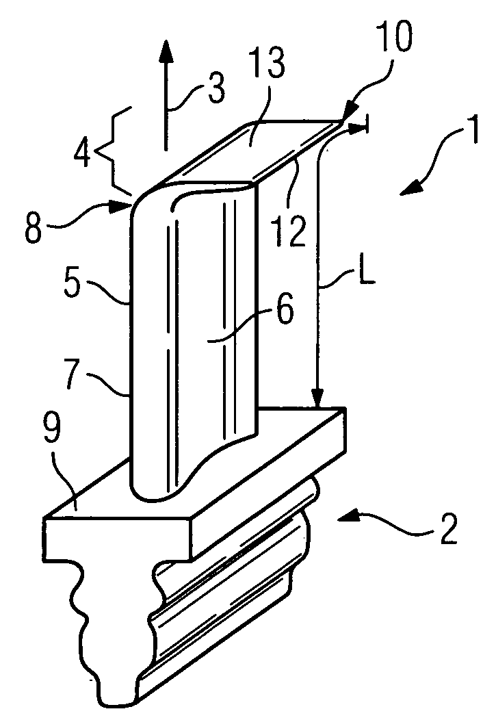
[0023]In FIG. 1, a turbine blade 1 is to be seen in perspective view. The turbine blade has a blade root 2 which is suitable for fastening in a rotor, which is not shown. In this case, the blade root has a so-called fir-tree root shape. Further embodiments for the blade root 2 are known, such as the hook-type root embodiment or T-shaped root embodiment. Such turbine blades 1 can be used in turbomachines such as steam turbines, gas turbines or compressors. The turbine blade 1 is formed along a radial direction 3 and has a blade tip 4 and also a blade profile with a pressure side 6 and a suction side 7.

[0024]The blade tip 4 of the turbine blade 1 has a curvature 8. The curvature 8 in this case is localized on the upper region of the blade tip 4. The curvature 8 is formed as a bend, as a result of which the blade tip is formed in the manner of a winglet, which is known from aircraft construction. The blade 1 has an overall length L which can be calculated from the surface of the blade ...


PUM


Abstract

There is described a blade for a turbomachine, such as a steam turbine. The blade has a blade tip, which is curved in relation to the blade airfoil profile. The curvature has the shape of a winglet, which is known from aircraft construction.

Description

CROSS REFERENCE TO RELATED APPLICATIONS[0001]This application claims priority of European Patent Office application No. 07002465.8 EP filed Feb. 5, 2007, which is incorporated by reference herein in its entirety.FIELD OF INVENTION[0002]The invention relates to a blade for a turbomachine, wherein the blade is formed along a radial direction and has a blade tip and also a blade profile with a pressure side and a suction side.BACKGROUND OF INVENTION[0003]Free standing lowpressure blades are used in turbomachines, such as in steam turbines, primarily in the low-pressure region. For constructional reasons, such turbomachines have a comparatively large radial gap between the blade tip and the casing. So that losses, however, do not become too great, it is known to arrange abrasive coatings on the blade tip or on the casing which lies opposite the blade tip. With contact between the blade tip and the casing, only the abrasive coating is slightly worn away, as a result of which a comparativ...

Claims


Application Information

Patent Timeline
IPC IPC(8): F01D5/14
CPCF01D5/20Y02T50/673F04D29/681F04D29/324Y02T50/60
Inventor NEEF, MATTHIASSURKEN, NORBERTLAZZER, ARMIN DE
Owner SIEMENS AG
Why Eureka
Try Eureka