Non-aqueous electrolyte secondary battery

a secondary battery and electrolyte technology, applied in the field of non-aqueous electrolyte secondary batteries, can solve the problems of insufficient electrical contact, inability to contribute, and the decline in battery capacity cannot be curbed sufficiently, and achieve excellent charge and discharge cycle life performance, the effect of preventing capacity declin

Inactive Publication Date: 2008-09-04
PANASONIC CORP
View PDF3 Cites 16 Cited by
  • Summary
  • Abstract
  • Description
  • Claims
  • Application Information

AI Technical Summary

Benefits of technology

[0006]The present invention aims to provide a non-aqueous electrolyte secondary battery which is excellent in charge and discharge cycle life performance and in which capacity decline is prevented even with repetitive charge and discharge cycles.
[0010]Inventors of the present invention further pursued research based on such findings. As a result, the inventors of the present invention achieved obtaining a non-aqueous electrolyte secondary battery which has excellent charge and discharge cycle life performance and which achieves curbing capacity decline due to the disintegration of the positive electrode active material and due to metal ions leached out from the positive electrode active material without impairing performance other than battery capacity, by using a positive electrode active material in a dispersed state as primary particles, and by providing a porous film at a specific portion of the non-aqueous electrolyte secondary battery, thereby completing the present invention.
[0028]By using the positive electrode active material in dispersed state as primary particles, the secondary particles with grain boundary are not be present, and therefore even though the primary particles are expanded and contracted during charge and discharge cycles, electrically non-conductive primary particles will not be generated. Thus, decline in battery capacity involved with charge and discharge cycles is minimized. Additionally, by providing a porous film at a specific portion, even though the primary particle positive electrode active material is used, the metal ions leached out from the positive electrode active material surface are captured by the porous film by priority, and therefore the metal ion attachment (precipitation) and deposition to the negative electrode active material surface can be curbed, and thus the decline in battery capacity is prevented. These effects are notable when using 80 wt % or more of the positive electrode active material dispersed as primary particles. Therefore, in a non-aqueous electrolyte secondary battery of the present invention, capacity decline is excellently curbed even with repetitive charge and discharge cycles; charge and discharge cycle life performance is excellent; and life is longer compared with conventional non-aqueous electrolyte secondary batteries.

Problems solved by technology

The disintegration of the secondary particles generates primary particles that have insufficient electrical contact and are unable to contribute to charge and discharge reaction.
However, inventors of the present invention found out in their research that decline in battery capacity cannot be curbed sufficiently and charge and discharge cycle life performance cannot be improved to the point of satisfaction just by using the primary particles of the positive electrode active material.
Thus, the decline in battery capacity becomes notable.

Method used


Image

  • Non-aqueous electrolyte secondary battery
  • Non-aqueous electrolyte secondary battery
  • Non-aqueous electrolyte secondary battery

Examples


example 1

(1) Positive Electrode Active Material Preparation

[0079]An aqueous solution with a metal ion concentration of 2 mol / L was prepared by adding Co and Al sulfates to a NiSO4 aqueous solution, so that the molar ratio between Ni, Co, and Al is Ni:Co:Al=7:2:1. A sodium hydroxide solution with a molar concentration of 2 mol / L was gradually dropped to this aqueous solution for neutralization, to produce a ternary precipitate having the composition represented by Ni0.7Co0.2Al0.1(OH)2 with a coprecipitation method. The precipitate was separated by filtering, washed with water, and dried at a temperature of 80° C., to obtain a composite hydroxide. The average particle size of the obtained composite hydroxide determined by a particle size distribution analyzer (product name: MT3000, manufactured by Nikkiso Co., Ltd.) was 10 μm.

[0080]This composite hydroxide was heat-treated in an atmosphere at 900° C. for 10 hours, to obtain a ternary composite oxide having a composition represented by Ni0.7Co0...

example 2

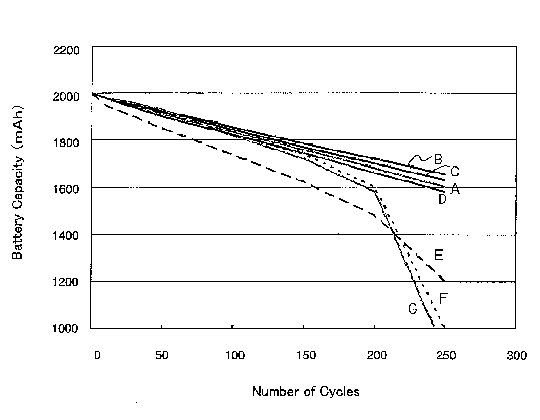
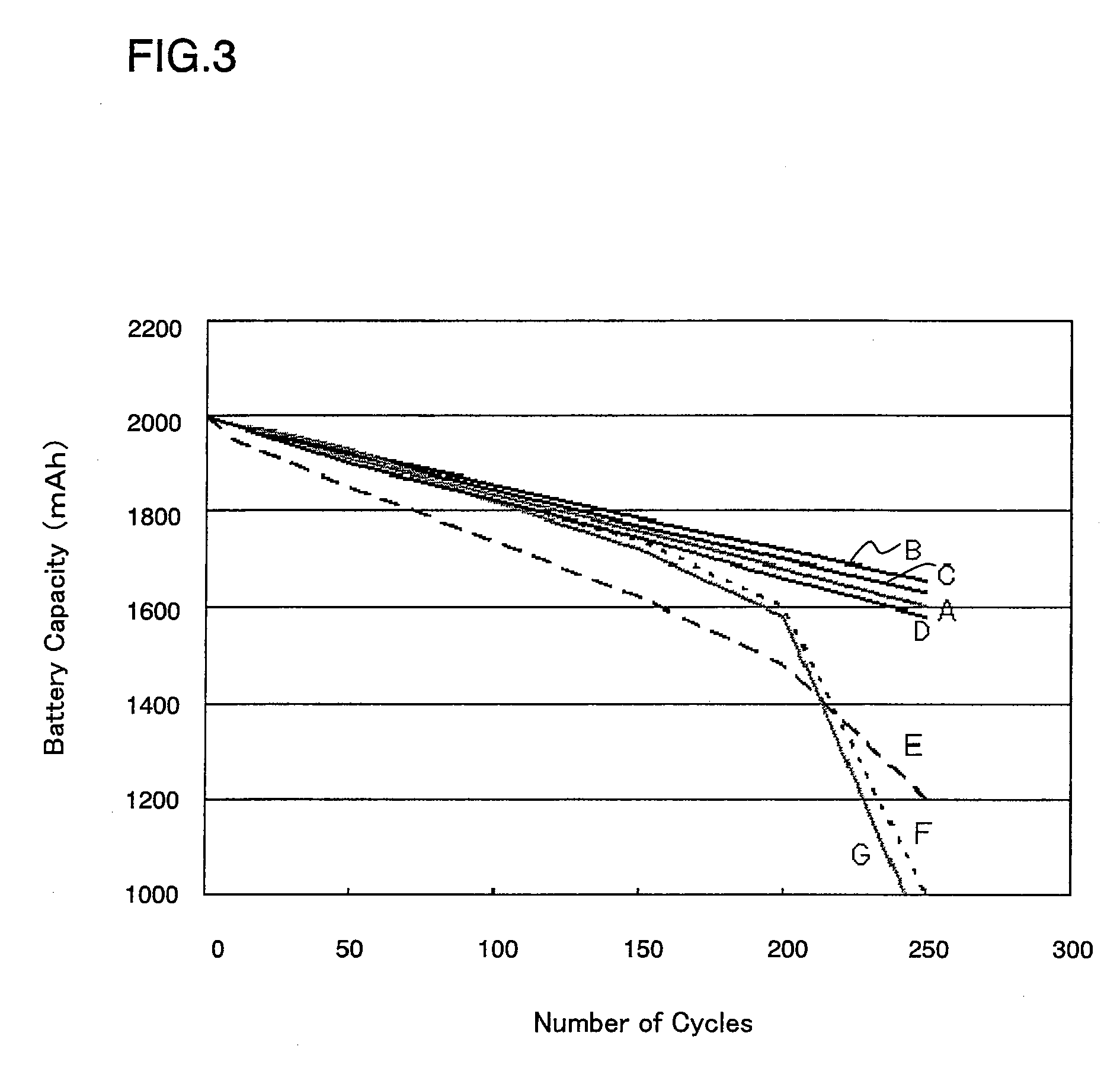
[0087]Cylindrical battery B of the present invention was made in the same manner as Example 1, except that the porous film was formed on both sides of the negative electrode surface instead of the positive electrode.

example 3

[0088]Cylindrical battery C of the present invention was made in the same manner as Example 1, except that the porous film was formed and disposed on one surface of the separator instead of the positive electrode, so as to allow the positive electrode to face the porous film on the separator surface when assembling the electrode assembly.


PUM

PropertyMeasurementUnit
particle sizeaaaaaaaaaa
energy densityaaaaaaaaaa

Abstract

In a non-aqueous electrolyte secondary battery including an electrode assembly including a positive electrode containing a positive electrode active material, a negative electrode containing a negative electrode active material, and a separator interposed therebetween; and a non-aqueous electrolyte, 80 wt % or more of the positive electrode active material is primary particles, and the separator is formed by a porous film, or the porous film is formed at at least one position from the following: between the positive electrode and the separator main body, between the negative electrode and the separator main body, and inside the separator main body, to capture the metal ions leached from the positive electrode active material. Such an arrangement enables a non-aqueous electrolyte secondary battery with significantly less decline in battery capacity, excellent charge and discharge cycle life performance, and capable of stable output for a longer period of time.

Description

FIELD OF THE INVENTION[0001]The present invention relates to non-aqueous electrolyte secondary batteries. To be more specific, the present invention mainly relates to improvement in a positive electrode active material.BACKGROUND OF THE INVENTION[0002]Nowadays, electronic devices, especially small consumer electronic devices are increasingly becoming portable and wireless at a fast pace, and for power sources for driving these devices, development of small, lightweight, high-energy density, and long-life secondary batteries is strongly desired. In addition to small consumer electronic devices, there has been rapid-pace development of technology for large secondary batteries used for electrical energy storage and electric cars, which require long-term durability and safety. In view of the foregoing, non-aqueous electrolyte secondary batteries, particularly, lithium secondary batteries are expected as a power source for electronic devices, electrical energy storage, and electric cars,...

Claims


Application Information

Patent Timeline
Patent Type & Authority Applications(United States)
IPC IPC(8): H01M4/40H01M2/14H01M4/485H01M4/505H01M4/525H01M10/0525H01M50/451H01M50/489H01M50/491
CPCH01M2/166H01M2/1686H01M4/02Y02E60/122H01M4/485H01M10/0525H01M2004/021H01M4/131Y02E60/10H01M50/446H01M50/451H01M50/489H01M50/491
Inventor OKADA, YUKIHIROFUJITA, HIDEAKI
Owner PANASONIC CORP
Why Eureka
Try Eureka