Dental Implant Fixture

Inactive Publication Date: 2008-09-04
RHEW ILL MO
View PDF7 Cites 11 Cited by
  • Summary
  • Abstract
  • Description
  • Claims
  • Application Information

AI Technical Summary

Benefits of technology

[0016]The dental implant fixture of the present invention which has the inclined R/S border to the plane perpendicular to the long axis of the dental implant fixture, is remarkably effective in preventing any reduction in the implant stability caused by a bone removal procedure in patients havin

Problems solved by technology

In particular, when a dental implant fixture having rough surface is exposed to the outside of the soft tissue barrier, which defends against bacterial invasion, the roughness of the surface causes accumulation of plaque (bacterial membrane on the tooth surface) more easily than the smooth surface, thus inducing periodontitis and subsequent loss of alveolar bone, and also increasing the risk of implant failure in the long term (Kim and Hwang, ibid.).
Such placement protocols have been established because exposure of the rough surface of the dental implant fixture to the bacteria in oral cavity could be fatal to the survival of implant (FIG. 2).
However, the above-described method of removing the protruded part of bone involves placement of a dental

Method used


Image

  • Dental Implant Fixture
  • Dental Implant Fixture
  • Dental Implant Fixture

Examples


Embodiment Construction

[0029]Hereinafter, embodiments of the present invention will be described in more detail with reference to attached drawings.

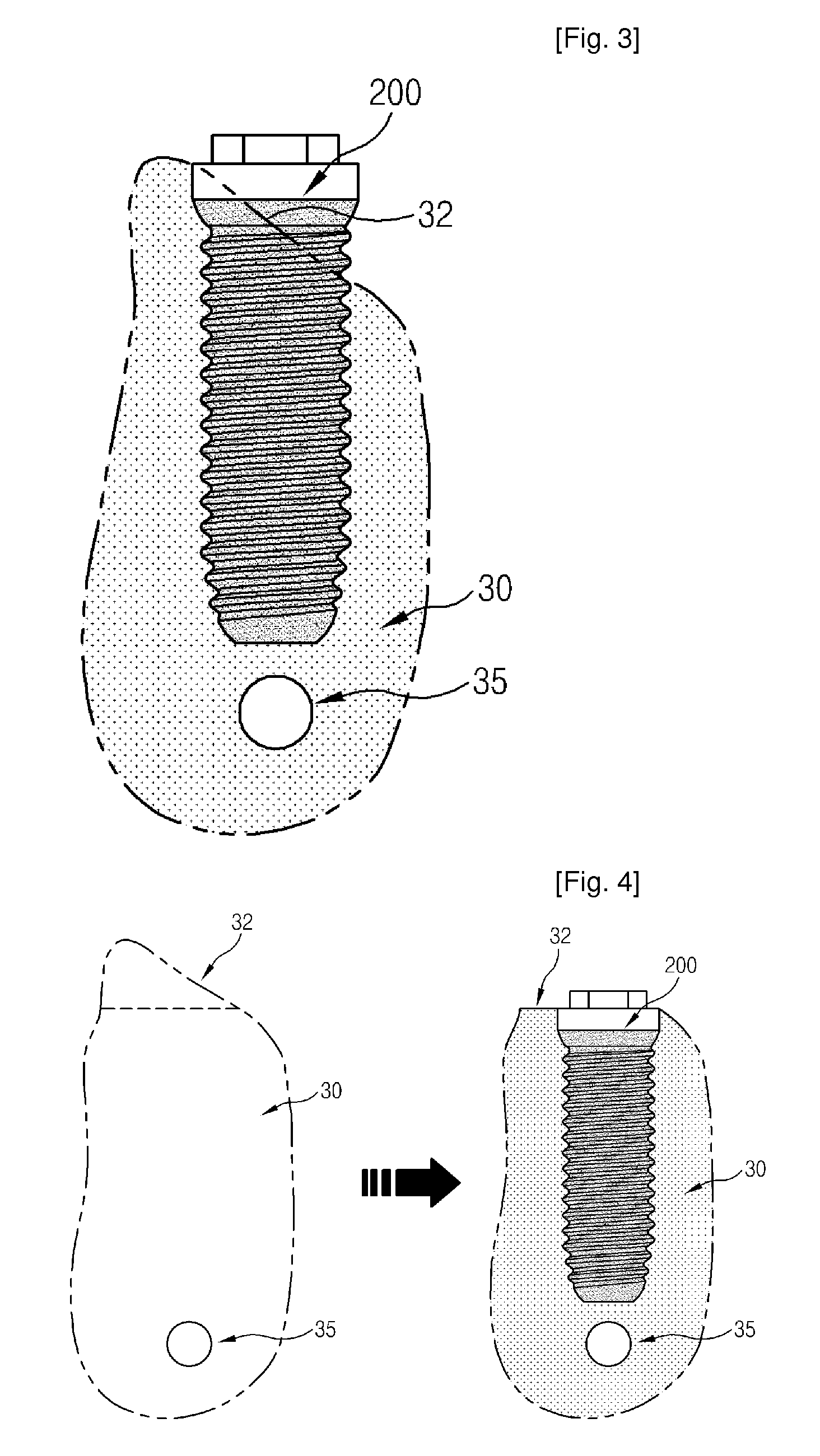
[0030]FIG. 6 is a diagram illustrating the status of a dental implant fixture according to an embodiment of the present invention placed in a bone having inclined bone crest. As illustrated in FIG. 6, the R / S border of the dental implant fixture of the present invention is formed at an angle to the horizontal. Such formation of the R / S border is intended, when placing a dental implant fixture in a not too excessively inclined bone crest, to place the rough surface of the dental implant fixture inside the bone without removing any protruded bone part or performing guided bone regeneration.

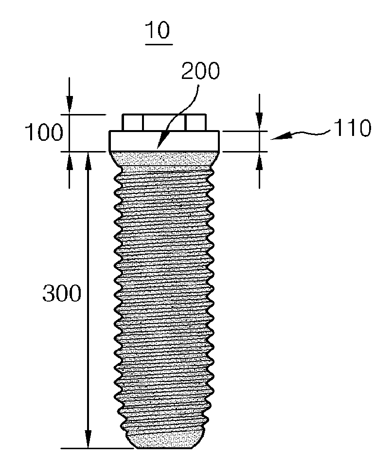
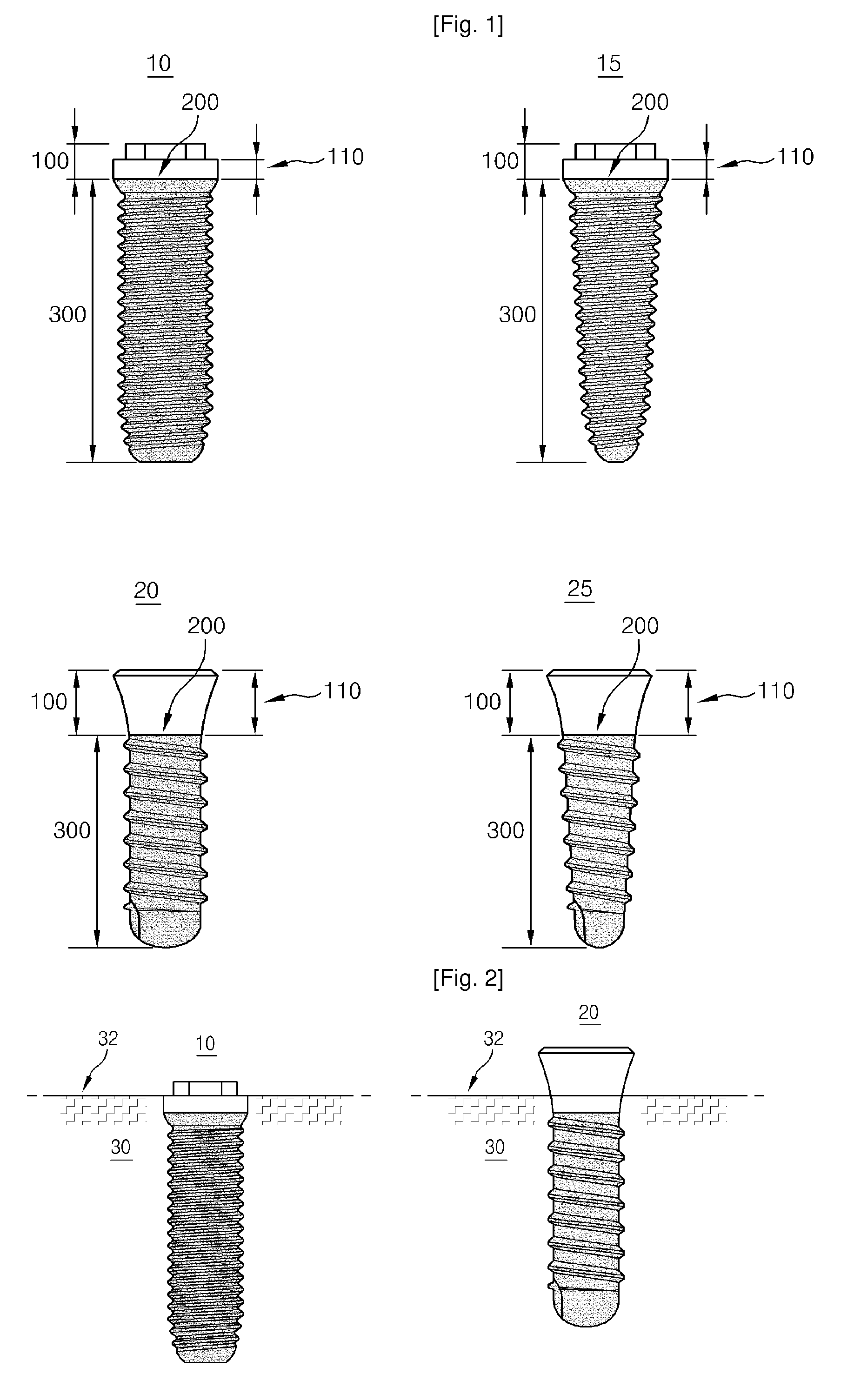
[0031]To this end, the dental implant fixture 10 or 20 of the present invention comprises a rough-surfaced lower part 300 having a predetermined roughness and a smooth-surfaced upper part 100 having a roughness lower than the roughness of the rough-surfaced lower part, and a p...


PUM


Abstract

The present invention provides a fixture for a dental implant that serves as a replacement for a missing tooth and is implanted in the maxillary or mandibular bone. In this fixture invention the R/S border (the border between the rough and smooth surfaces) is formed to be inclined to a plane perpendicular to the long axis (central axis) of the dental implant fixture. The dental implant fixture prevents a marked decrease in the support for the dental implant due to bone reduction procedure in a patient having inclined bone crest, eliminates disadvantages in the aspects of expenses caused by the application of guided bone regeneration technique and also removes inconvenience of long operation time and possible infection, and also has a remarkable advantage of making convenient one-staged surgery possible in many cases.

Description

TECHNICAL FIELD[0001]The present invention relates to the fixture of a dental implant that serves as a replacement for a missing tooth by being implanted in human maxillary or mandibular bone. In particular, this invention provides a dental implant fixture in which the border between the rough and smooth surfaces is fabricated to be inclined, for the treatment of patients having inclined bone crest on maxilla or mandible.BACKGROUND ART[0002]A dental implant is an artificial structure designed to replace a missing tooth. An artificial tooth root part of a dental implant, which is composed of biologically inert material, is made to be embedded and to adhere to the alveolar bone of the missing tooth. An artificial tooth crown part of a dental implant is then connected onto the artificial dental root so as to restore the original function of the missing tooth. A dental implant fixture is the artificial dental root part of a dental implant, which is made to be placed into the alveolar bo...

Claims


Application Information

Patent Timeline
IPC IPC(8): A61C13/00
CPCA61C8/0012A61C8/0077A61C8/0022A61C8/00
Inventor RHEW, ILL-MO
Owner RHEW ILL MO
Why Eureka
Try Eureka