

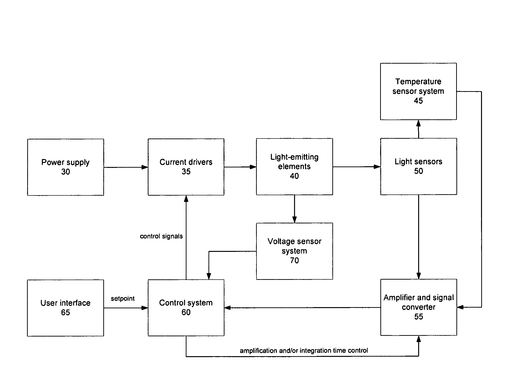
Luminaire control system and method
a control system and light source technology, applied in the field of light source, can solve the problems of undesired light effects in feedback-controlled multi-color led based systems, insufficiently accurate responsivities, and inability to provide practical useful indications of cie tristimulus values
- Summary
- Abstract
- Description
- Claims
- Application Information
AI Technical Summary
Benefits of technology
Problems solved by technology
Method used
Image

Examples
example 1
[0053]In a first example, the control system can be configured to read the RGB sensor data [R G B] and apply a predetermined transformation in order to derive approximate values of the CIE tristimulus values X, Y and Z of the light emitted by the LEEs. This can be performed by, for example, programming the control system with the linear algebraic relation
[XYZ]=[RGB]T (3)
using the 3×3 transformation matrix
T=(NTN)−1NTM=N+M (4)
NT is the transpose and N+ is the pseudoinverse of N. M is an n×3 matrix of ideal tristimulus values Mij and N is a corresponding n×3 matrix of RGB color sensor data for the same set of n SPDs. M and N can be determined during a calibration step that utilizes the n SPDs and characterizes them with the RGB color sensors to determine N and, for example, with an accurately calibrated spectrometer to determine M. T can subsequently be determined, for example, through a least squares solution, by minimizing the error function
=∑i=1n∑j=13(Mij-[NT]ij)2(5)
This method ca...
example 2
[0060]In another embodiment, it may be advantageous in terms of computational efficiency to operate the control system using feedback raw RGB sensor data directly. In such an embodiment, it is no longer necessary for the control system to transform the RGB sensor data each time it is fed back. Instead the user-specified input data is transformed into RGB sensor coordinates from coordinates such as XYZ tristimulus or xyY chromaticity and intensity, for example, in order for the control system to compare the setpoint with the RGB color feedback data. In such an embodiment, a transformation needs to take place only when the user-specified input data changes. In this embodiment the control system operates in RGB sensor coordinates to set and maintain desired chromaticity and intensity.
[0061]For a predetermined transformation T, the target RGB values can be determined from:
[RTGTBT]=[XYZ]T−1 (11)
It is noted that the transformation T used in Equation 11 may the determined as described abo...
example 3
[0063]In this embodiment the controller is configured to transform each of one or more predetermined RGB sensor data into a respective predetermined desired color space, for example XYZ data while the rest of a training set of the RGB sensor data is transformed as described even if the average least squares error for the rest of the data is increased. This embodiment may be utilized to ensure that the control system can perform a calibration process that preserves white light RGB sensor data as such.
[0064]The additional constraint for the calibration method can be expressed as Mw=NwT where Nw is the RGB sensor data of the predetermined “white” SPD, and Mw are the corresponding XYZ tristimulus values. The transformation matrix can be determined by:
Tj=(NTN)-1NTMj+(1-MjTN[NTN]-1Nw)(NwT[NTN]-1Nw)[NTN]-1Nw(12)
where Tj is the ith column of T, Mj is the jth column of M, and Mw=[1 1 1].
[0065]In one embodiment the controller is configured with CIE 1976 UCS color space coordinates u′ and v′ a...
PUM
 Abstract
Description
Claims
Application Information