Grounding Wire Structure Having Stainless Steel Covering and Method of Manufacturing the Same

a technology of grounding wire and stainless steel, which is applied in the direction of insulated conductors, rigid-tube cables, cables, etc., to achieve the effects of superior electrical conductivity, superior durability of grounding wire structure, and preventing bursting

Inactive Publication Date: 2008-09-11
KIM KUI YEUN
View PDF0 Cites 15 Cited by
  • Summary
  • Abstract
  • Description
  • Claims
  • Application Information

AI Technical Summary

Benefits of technology

[0009]In the grounding wire structure according to the present invention, because a covering pipe for a grounding wire is made of stainless steel, the durability of the grounding wire structure is superior. Furthermore, the interior of the stainless steel covering pipe maintains the vacuum state without moisture, so that it is prevented from bursting due to heat expansion or from freezing and thus bursting. Because graphite, which has superior electric conductivity and a melting point of 3000° C. or more, which is sufficient to prevent thermal deformation, is used, the durability of a discharge tip is increased. As well, in addition to being environmentally friendly, the product is standardized, thus errors are prevented from occurring in the design and construction work of laying the grounding wire, thus there is an advantage in that construction costs are reduced. Even in a marshy region, the grounding wire structure of the present invention can maintain the durability thereof. As such, the present invention provides an effective and economical grounding wire structure having the stainless steel covering.

Problems solved by technology

, there is a problem in that, due to the penetration of moisture, it may burst due to heat expansion or freeze and thus burst.

Method used


Image

  • Grounding Wire Structure Having Stainless Steel Covering and Method of Manufacturing the Same
  • Grounding Wire Structure Having Stainless Steel Covering and Method of Manufacturing the Same
  • Grounding Wire Structure Having Stainless Steel Covering and Method of Manufacturing the Same

Examples


Embodiment Construction

[0013]Hereinafter, the construction and operation of the present invention will be described in detail with reference to the attached drawings.

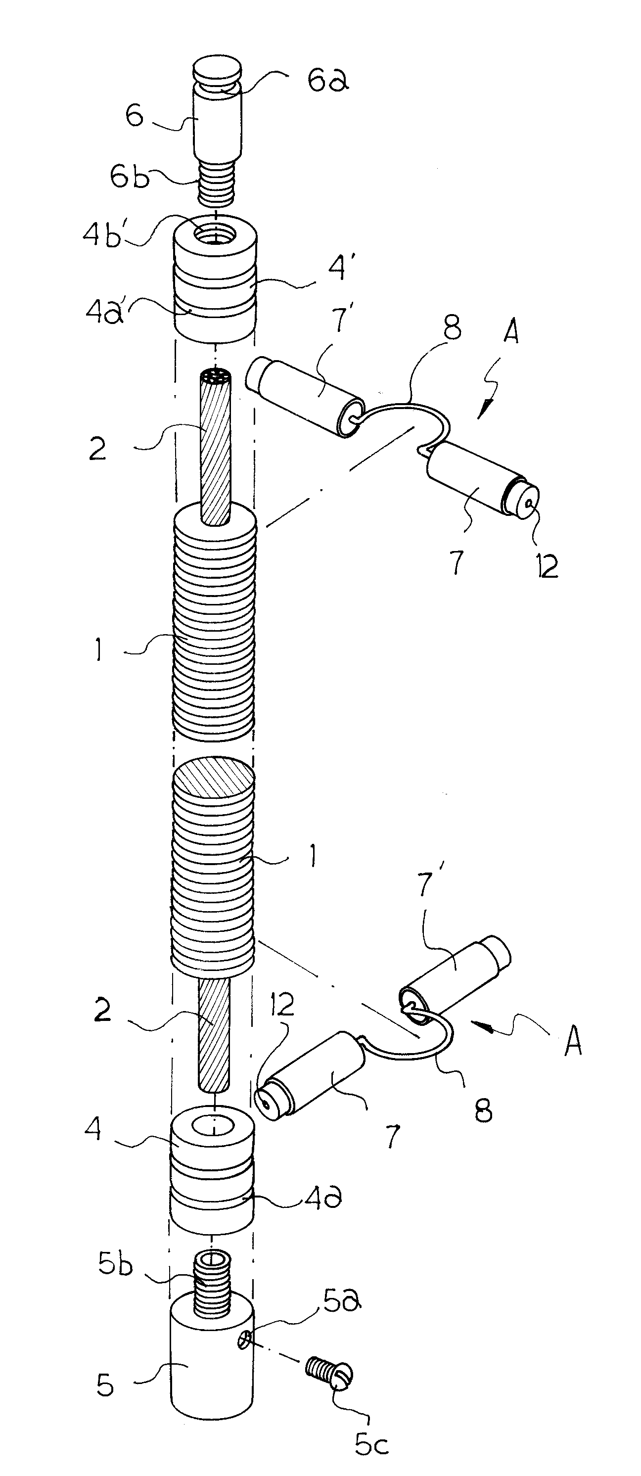
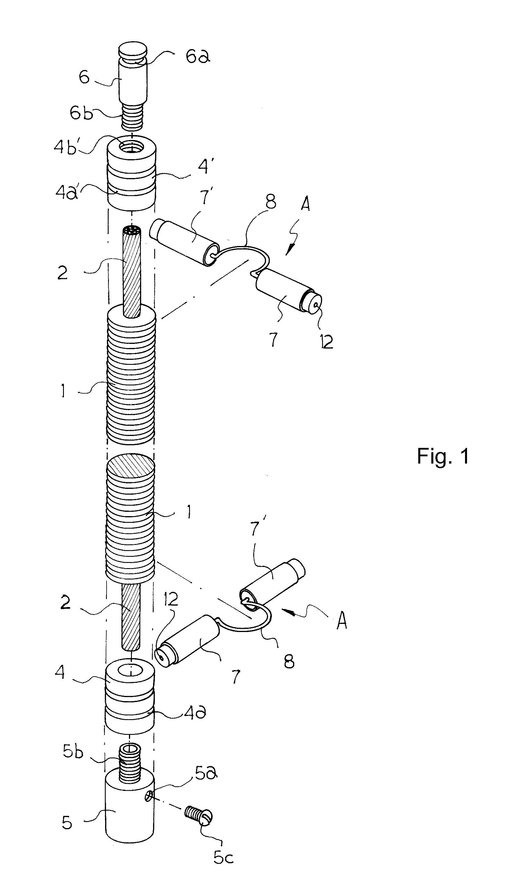
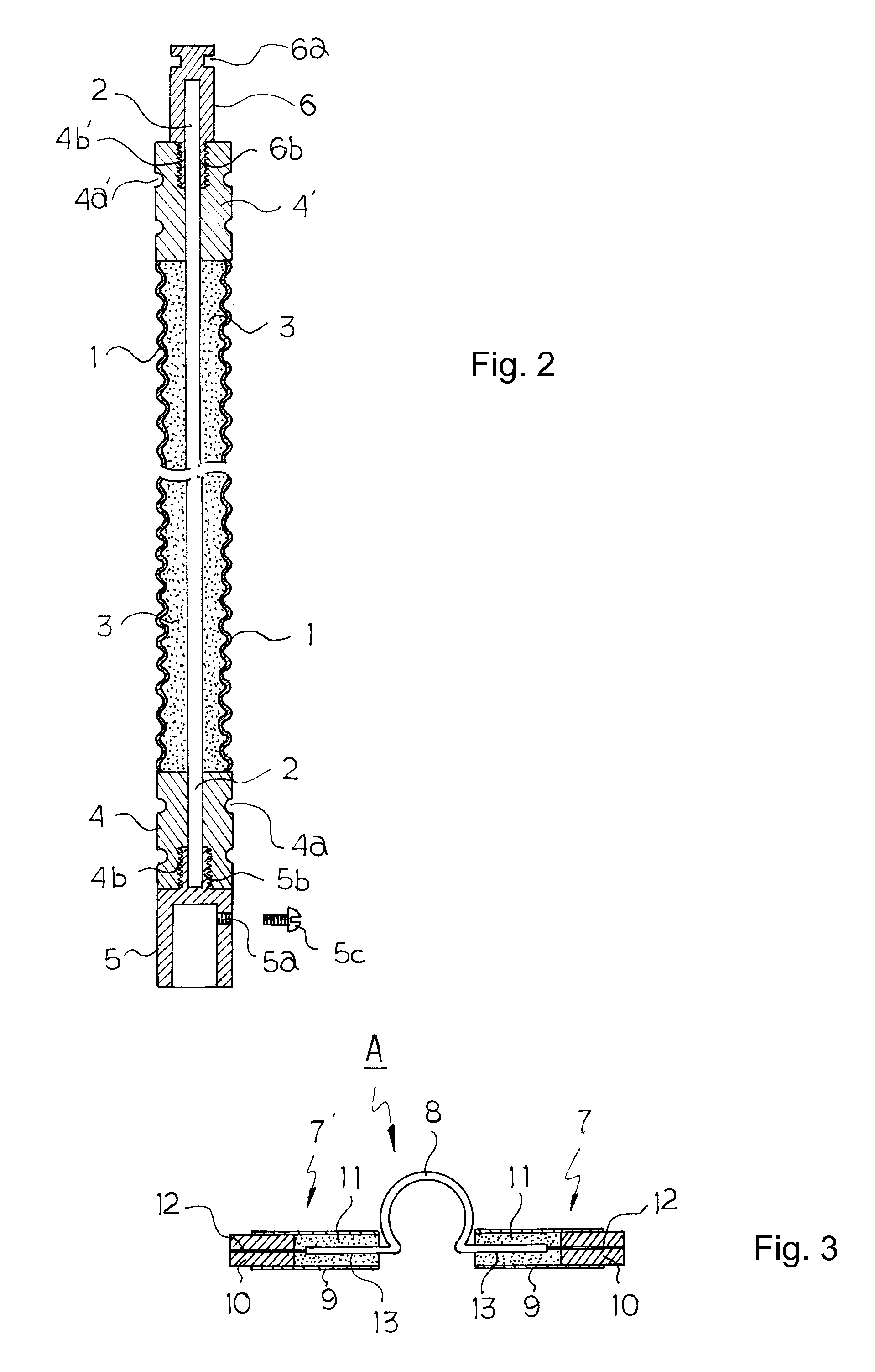
[0014]FIG. 1 is an exploded perspective view of a cut portion of a grounding wire structure according to the present invention, showing the construction in which connection frames are coupled to the upper and lower ends of a stainless steel covering pipe that covers a grounding wire, a connection socket and a connection rod are coupled to the respective connection frames, and discharge tip assemblies, in each of which discharge tip bodies are coupled by a connection pin, are fitted over the covering pipe at intervals of 5 cm. FIG. 2 is a sectional view of the cut portion of the ground wire structure according to the present invention, showing the connection frames, the connection socket and the connection rod which are coupled to the opposite ends of the covering pipe, which is filled with graphite and ground resistance reducing material, or ...


PUM

PropertyMeasurementUnit
temperatureaaaaaaaaaa
diameteraaaaaaaaaa
melting pointaaaaaaaaaa

Abstract

The present invention provides a grounding wire structure having a stainless steel covering and a method of manufacturing the grounding wire structure. In the present invention, first and second hollow connection frames (4) and (4′), each of which has a compressing groove (4a), (4a′) and an internal thread (4b), (4b′), are coupled to respective opposite ends of a stainless steel pipe (1), in which a grounding wire (2) is provided, and which is filled with graphite (3). Corrugated grooves are formed in the outer surface of the stainless steel pipe (1). A connection socket (5) is coupled to the internal thread (4b) of the first connection frame (4). A connection rod (6) is coupled to the internal thread (4b′) of the second connection frame (4′). Discharge tip assemblies (A), each of which has discharge tip bodies (7) and (7′) connected to each other through a connection pin (8), are fitted over the corrugated grooves of the stainless steel covering pipe (1).

Description

TECHNICAL FIELD [0001]The present invention relates to a grounding wire structure, which has a stainless steel covering and is used to prevent lightning damage, and a method of manufacturing the grounding wire structure.BACKGROUND ART [0002]In the conventional art, grounding wire is laid to a length ranging from 20 m to 40 m, and to prevent corrosion, concrete including grounding resistance reducing material is applied to the grounding wire to a thickness of 10 cm and a width of 40 cm to protect the grounding wire and to increase the discharge area. Furthermore, concrete is applied to the grounding wire to increase the discharge area. In a region where discharge is difficult depending on geographical conditions, for example, in a region where there are many rocks or a lot of gravel, a separate needle-shaped stainless steel grounding rod for additional grounding is provided to govern spark discharge.[0003]However, in the conventional art, because concrete mixed with resistance reduci...

Claims


Application Information

Patent Timeline
Patent Type & Authority Applications(United States)
IPC IPC(8): H01R4/66H01R43/00
CPCH01B7/16Y10T29/49117H01R4/66H01R4/62H01B3/105H01B7/20H02G13/40
Inventor KIM, KUI-YEUN
Owner KIM KUI YEUN
Why Eureka
Try Eureka