
Gas Sensor

Inactive Publication Date: 2008-09-11
ROBERT BOSCH GMBH
View PDF10 Cites 12 Cited by
  • Summary
  • Abstract
  • Description
  • Claims
  • Application Information

AI Technical Summary

Benefits of technology

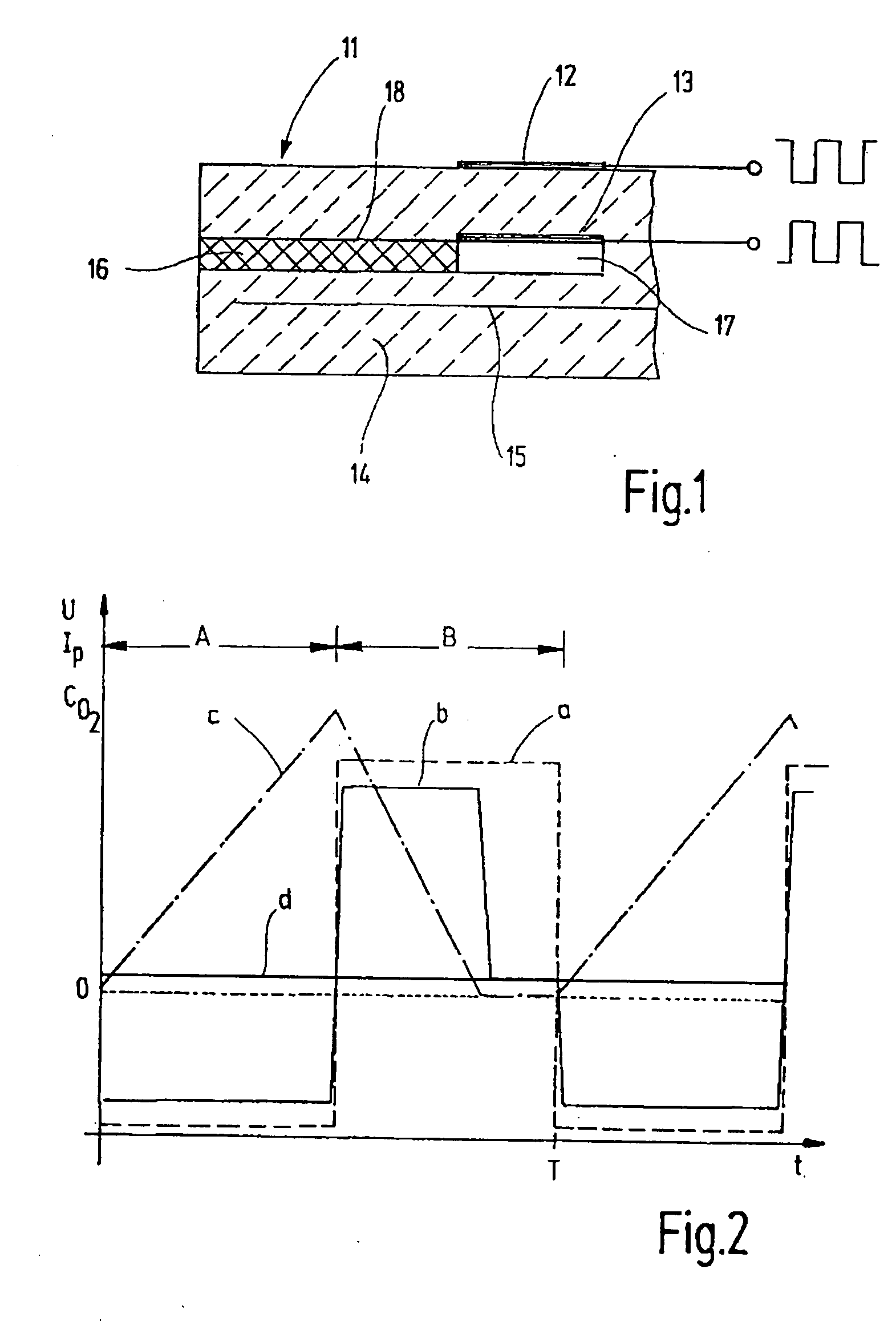
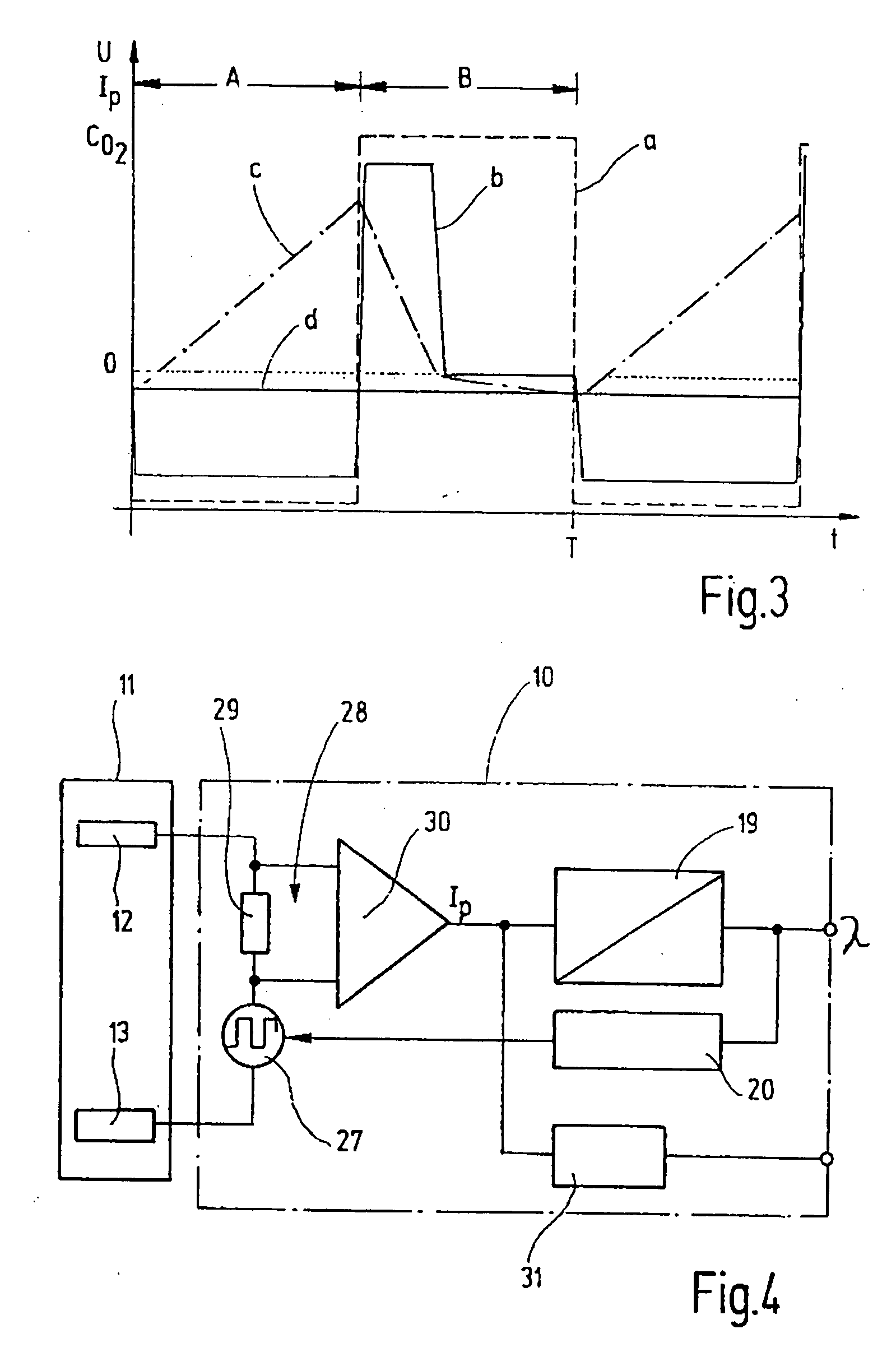
[0004]The gas sensor according to the exemplary embodiment and / or exemplary method of the present invention has the advantage of a considerably higher measuring accuracy in determining the concentration of the gas components in the measuring gas, in particular in determining the oxygen concentration or the air / fuel ratio (λ) in exhaust gases. The provision of the cavity between diffusion barrier and the inner pump electrode situated on the solid-state electrolyte produces a region having a constant oxygen concentration, which serves as storage volume. In contrast to the gas sensor described in the introduction, the oxygen must therefore not be stored in the diffusion barrier, which shortens the diffusion barrier and falsifies the measuring signal due to the shortened diffusion barrier. Like the known gas sensor described in the introduction, the gas sensor according to the exemplary embodiment and / or exemplary method of the present invention has only two electrodes, which allows a cost-effective production and a wide λ-measuring range, which has been considerably expanded into the enriched range of the exhaust gas. Operating the electrodes with a varying potential improves their pumping ability for oxygen.
[0007]According to one advantageous specific embodiment of the present invention, the oxygen quantity delivered into the cavity in the pump-in phase is controlled as a function of the instantaneous oxygen concentration in the measuring gas. This not only results in the desired broadening of the measuring range in the rich range of an exhaust gas, but also greatly reduces the pumped-in oxygen quantity in the lean range of the exhaust gas so as not to stress the pump electrodes unnecessarily.

Problems solved by technology

This not only results in the desired broadening of the measuring range in the rich range of an exhaust gas, but also greatly reduces the pumped-in oxygen quantity in the lean range of the exhaust gas so as not to stress the pump electrodes unnecessarily.

Method used


Image

  • Gas Sensor
  • Gas Sensor
  • Gas Sensor

Examples


Embodiment Construction

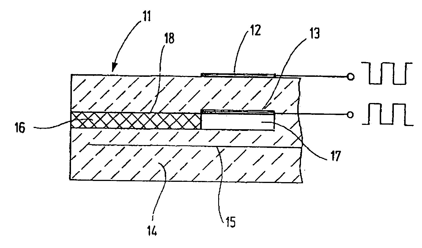
[0018]The gas measuring probe or gas sensor described here is used to determine the concentration of a gas component in a measuring gas, and may be employed as Lambda sensor for determining the oxygen concentration in the exhaust gas of internal combustion engines by which the air / fuel ratio in the exhaust gas of internal combustion engines, which is indicated as so-called λ-value, is ascertained. The following description therefore relates to such a gas sensor for determining the λ value.

[0019]The gas-measuring probe or gas sensor has a sensor element 11, shown in FIG. 1 in schematized form in longitudinal section, which is usually accommodated in a housing and exposed to the exhaust gas by its gas-sensitive portion. Situated in the gas-sensitive portion is an electrode pair, which is connected to a connector cable routed out of the housing and to a control device 10 (FIG. 4) with the aid of circuit traces and a connector plug. The electrode pair encompasses an outer pump electrode...


PUM


Abstract

A gas sensor is provided for determining the concentration of a gas component in a measuring gas, in particular for determining the oxygen concentration in the exhaust gas of internal combustion engines, which has an electrode pair situated on a solid-state electrolyte and made up of an outer pump electrode and an inner pump electrode, which is accessible to the measuring gas supplied via a diffusion barrier, the electrode pairs being triggered in a clocked manner and having a potential of varying polarity applied in each clock-pulse period. To improve the measuring precision of the gas sensor without additional electrodes, a cavity is situated between the diffusion barrier and the inner pump electrode, the cavity serving as storage volume for the oxygen pumped through the solid-state electrolyte.

Description

FIELD OF THE INVENTION[0001]The present invention is based on a gas sensor for determining the concentration of a gas component in a measuring gas, in particular for determining the oxygen concentration in the exhaust gas of internal combustion engines.BACKGROUND INFORMATION[0002]In a gas-measuring probe or gas sensor for determining the λ-value in exhaust gases of internal combustion engines (M. Oshuga & Y. Ohyama “A study on the oxygen-biased wide range air-fuel ratio sensor for rich and lean air-fuel ratios”, Sensors and Actuators, 9 (1986), pages 287-300), the outer pump electrode of the electrode pair situated on the solid-state electrolyte is exposed to the atmosphere, and the inner pump electrode is covered by a diffusion barrier, which has an adapted thickness and is acted upon by the exhaust gas. The electrode pair is controlled in a clocked manner, and the inner pump electrode and the outer pump electrode are alternately connected to a potential of varying magnitude, which...

Claims


Application Information

Patent Timeline
IPC IPC(8): G01N27/26
CPCG01N27/4065G01N27/419G01N27/4071
Inventor KANTERS, JOHANNES
Owner ROBERT BOSCH GMBH
Learn More