Shaft assembly

a technology of shaft assembly and bearing module, which is applied in the direction of bearing module rigid support, mechanical equipment, mechanical energy handling, etc., can solve the problems of affecting the service life span affecting and causing abrasion and fatigue of the bearing module, so as to prolong the service life of the bearing module and support the rotational movement of the rotatable shaft. , the effect of simple structural configuration

Inactive Publication Date: 2008-09-11
SUN HUI
View PDF8 Cites 0 Cited by
  • Summary
  • Abstract
  • Description
  • Claims
  • Application Information

AI Technical Summary

Benefits of technology

[0008]A main object of the present invention is to provide a shaft assembly to solve the above problems, wherein the shaft assembly provides a simple structural configuration for being assembled and provides a rigid configuration for supporting the rotatable shaft. In addition, the mounting cavity does not require the precise configuration for the bearing module disposing therein. Therefore, the shaft assembly is adapted to prolong the service life span of the bearing module to supportively enhance the rotational movement of the rotatable shaft.
[0009]Accordingly, in order to achieve the above object, the present invention provides a shaft assembly which comprises a rotatable shaft, a bearing assembly, a lower supporting frame, and an upper supporting frame having a bearing cavity. The bearing assembly is disposed in the bearing cavity and is securely enclosed by the lower supporting frame when the lower supporting frame is coupled with the upper supporting frame. The bearing assembly comprises a first bearing rotor disposed in the bearing cavity of the upper supporting frame and a second bearing rotor supported by the lower supporting frame, wherein the first and second bearing rotors are positioned space apart from each other and are coaxially coupled with the rotatable shaft for enhancing a rotational movement of the rotatable shaft. A ring-shaped shaft guider is coupled between the first and second bearing rotors to retain a position of the bearing assembly is with respect to the rotatable shaft. In other words, the shaft guider is supported at a gap between the first and second bearing rotors. In addition, the upper supporting frame further has an upper platform shoulder formed at an upper wall of the bearing cavity 31 to engage an outer rotor ring of the first bearing rotor.
[0012]The rotatable shaft comprises a retention unit to prevent the rotatable shaft from being slid out of the bearing assembly. Accordingly, the rotatable shaft has a retention shoulder protruding radially and outwardly to supportively bias against the bottom surface of the second bearing rotor. A ring-shaped retention clip is coaxially mounted at the rotatable shaft at a position above the second bearing rotor to block the second bearing rotor from being moved along the rotatable shaft.
[0016]Accordingly, the present invention provides a simple assembling structure of the shaft assembly, wherein the bearing module is adapted to easily dispose in the mounting cavity because the size of the bearing cavity is larger than the size of the bearing module. Therefore, the user is able to couple the bearing module with the upper supporting frame without any difficulty. In addition, the bearing module is retained between the upper and lower supporting frames to prevent the bearing module from being detached during operation. The shaft guider is coupled between the first and second bearing rotors of the bearing module to retain a position of the bearing assembly with respect to the rotatable shaft. In other words, the bearing module does not require to tightly couple with the bearing cavity because the shaft guider is adapted to retain the position of the bearing module to engage with the rotatable shaft. In addition, once the bearing module is assembled in position, the shaft guider is adapted to prevent the vibration of the bearing module from the rotational movement of the rotatable shaft so as to prolong the service life span of the bearing module.
[0017]Accordingly, the manufacturing process and cost of the present invention is significantly lower. In other words, the assembling operation of the shaft assembly of the present invention is extremely easy, wherein the manufacturing process of the present invention can be simplified to substantially reduce the manufacturing cost thereof, so as to enhance the practice use of the present invention while being cost effective.
[0018]The present invention has a compact size in light weight. The size of the rotatable shaft can be minimized to provide a high speed and precise rotational output with minimum abrasion. Thus, the structural configuration of the present invention is suitable for mass production and is adapted to provide a stable rotational output with less noise and vibration so as to enhance the productivity of the shaft assembly.

Problems solved by technology

It is worth to mention that the size of the mounting slot will affect the service life span of the bearing module.
Accordingly, when there is a gap formed between the bearing module and the inner wall of the mounting slot, the rotational movement of the transmission shaft will cause the bearing module to vibrate so as to create an unwanted vibration of the bearing module within the mounting slot and to create an abrasion and fatigue of the bearing module.
However, it will substantially increase the manufacturing cost of the shaft assembly and will complicate the assembling operation of the shaft assembly, especially when the transmission shaft is extended in an off-center position.
As a result, such structural configuration of the shaft assembly is not suitable for mass production.

Method used


Image

  • Shaft assembly
  • Shaft assembly

Examples


Embodiment Construction

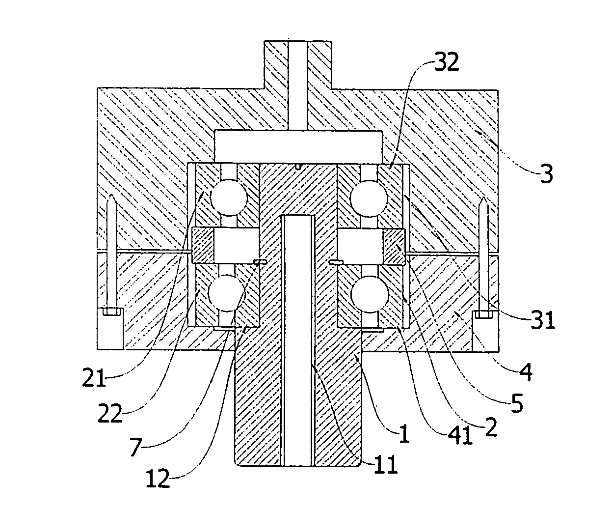
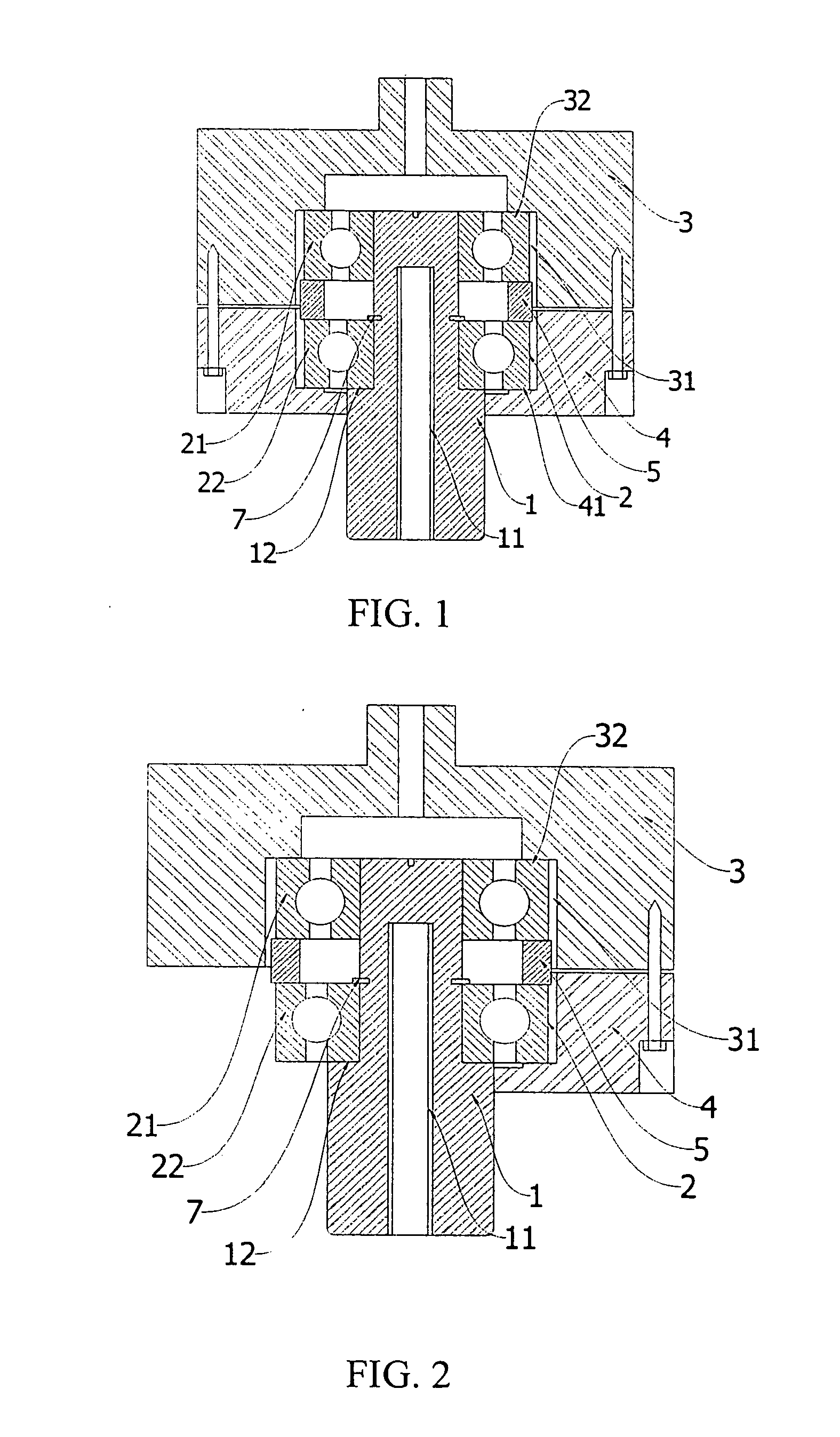
[0022]Referring to FIG. 1 of the drawings, a shaft assembly according to a preferred embodiment of the present invention is illustrated, wherein the shaft assembly comprises a rotatable shaft 1 having a circular cross section, a bearing module 2, a lower supporting frame 4 in which a lower portion of the rotatable shaft 1 is extended through the lower supporting frame 4, and an upper supporting frame 3 having a bearing cavity 31 in which an upper portion of the rotatable shaft 1 is extended within the bearing cavity 31 of the upper supporting frame 3. Accordingly, the bearing module 2, having an assemble structure, comprises a first bearing rotor 21 and a second bearing rotor 22 spacedly and coaxially coupling at the rotatable shaft 1. Each of the first and second bearing rotors 21, 22, having a ring shape, has an inner circumferential surface engaging with an outer circumferential surface of the rotatable shaft 1. In addition, each of the first and second bearing rotors 21, 22 has ...


PUM


Abstract

A shaft assembly includes a rotatable shaft, an upper supporting frame having a bearing cavity, a lower supporting frame coupling with the upper supporting frame, a bearing assembly, and a shaft guider. The bearing assembly includes a first bearing rotor disposed in the bearing cavity to coaxially engage with the rotatable shaft and a second bearing rotor coaxially engaging with the rotatable shaft, wherein a circumferential size of the bearing cavity is larger than an outer diameter of the bearing module. The shaft guider is coupled between the first and second bearing rotors to retain a position of the bearing assembly with respect to the rotatable shaft, wherein the shaft guider has an outer diameter smaller than the circumferential size of the bearing cavity and an inner diameter smaller than an outer diameter of each of the first and second bearing rotors.

Description

BACKGROUND OF THE PRESENT INVENTION[0001]1. Field of Invention[0002]The present invention relates to a rotational transmission device, and more particularly to a shaft assembly with a rotational axis and bearing module for use in the power tool for power transmission.[0003]2. Description of Related Arts[0004]According to the mechanical theory, a shaft assembly generally comprises a transmission shaft for transmitting a mechanical power and a bearing module for enhancing the mechanical movement of the transmission shaft. Accordingly, the bearing module not only maintains the transmission shaft in position to precisely move along its axis but also reduces a friction between transmission shaft and the supporting frame. Generally speaking, there are two types of transmission shaft, wherein one type the transmission shaft produces a sliding movement at the supporting frame while another type of the transmission shaft produces a rotational movement at the supporting frame.[0005]Accordingl...

Claims


Application Information

Patent Timeline
Patent Type & Authority Applications(United States)
IPC IPC(8): H02K5/16F16C3/00
CPCF16C35/06
Inventor ZHU, QI
Owner SUN HUI
Why Eureka
Try Eureka