
Eureka
For R&D, Eureka makes reading and utilizing patents & technical documents easy.
Eureka AIR
Designed for self-driven R&D workflows. Generate viable solutions, solve complex R&D challenges, empower your innovation with AI.

Eureka Materials
Designed for material experts only. Revolutionize your material R&D, from search, analyze, to developing new materials.

TechResearch
Generate reliable direction feasibility study reports for your R&D in just a few steps.

TechSeek
Discover and master advanced knowledge NOW. Basics, ideas, possibilities, all at once.

TechMind
As an expert in R&D Theories, TechMind can generates customized viable solutions instantly.

TechRisk
Analyze your overall solution with one click, know your potential R&D risks in advance.

TechMonitor
Get weekly tech updates, stay abreast of the latest tech innovations and key insights.
Power amplifier circuit, control method thereof and control program thereof
- Summary
- Abstract
- Description
- Claims
- Application Information
AI Technical Summary
Benefits of technology
Problems solved by technology
Method used
Image

Examples
second exemplary embodiment
2. Second Exemplary Embodiment
[0066]In the first exemplary embodiment mentioned above, negative feedback control of the power amplifier circuit is performed by an analog processing. However, the present invention can be realized by digital processing in negative feedback control.
2.1 Configuration and Operation of Second Exemplary Embodiment
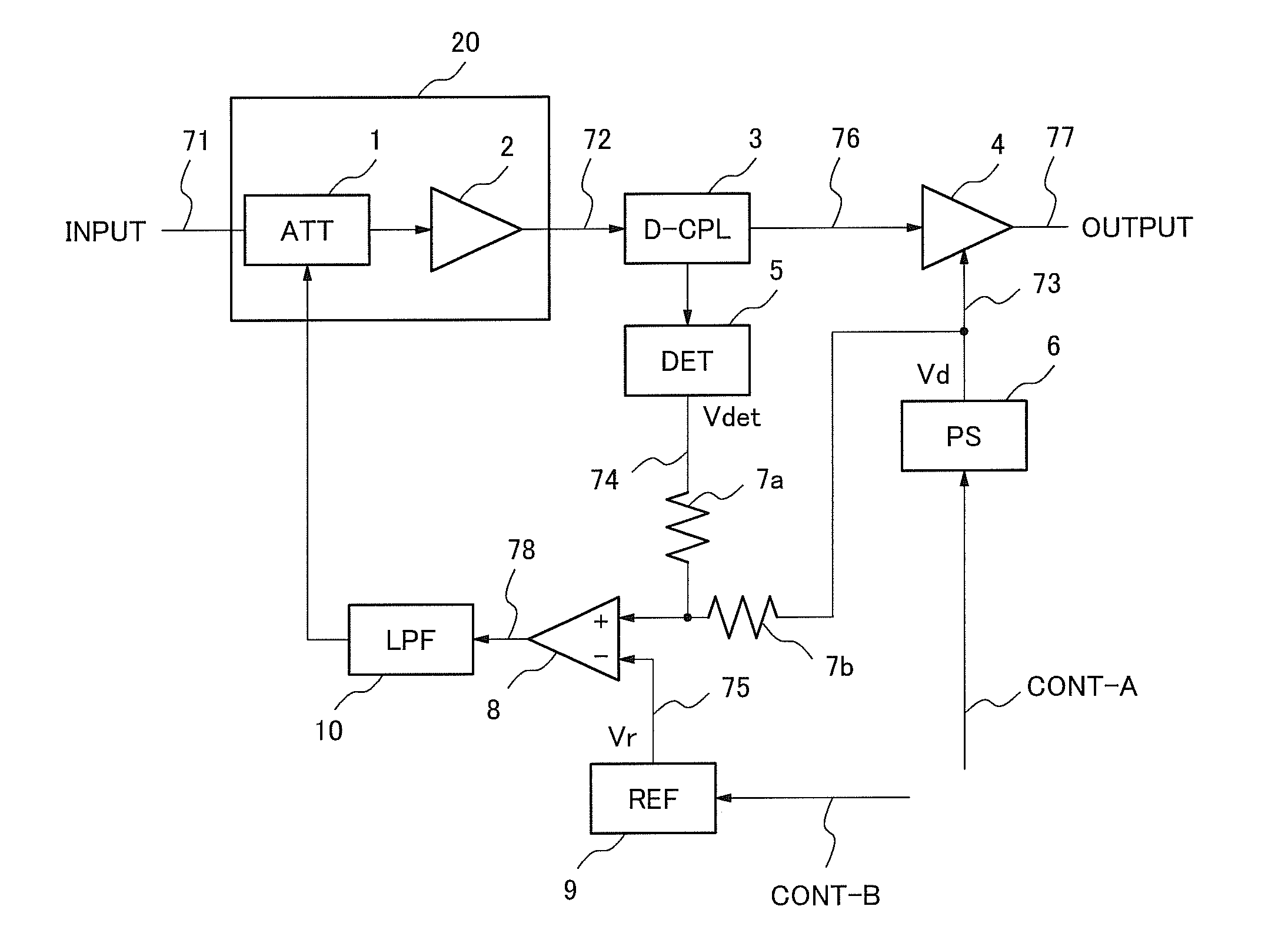
[0067]FIG. 10 shows the second exemplary embodiment of the present invention. According to the first exemplary embodiment shown in FIG. 1, the output of the operational amplifier (OP-AMP) 8 is outputted to the low pass filter (LPF) 10. The LPF 10 operates as an analog loop filter. According to the second exemplary embodiment, an output signal 91 of the OP-AMP 8 is outputted to an A / D converter (A / D) 11. A control signal (CONT-C) 93 for setting an output power of the power amplifier 4 enters a CPU 13. The CPU 13 processes an output signal 92 and the control signal 93 of the A / D 11 to generate a feedback signal 94 and implement a filtering function....
third exemplary embodiment
3. Third Exemplary Embodiment
3.1 Configuration and Operation of Third Exemplary Embodiment
[0070]FIG. 11 shows a third exemplary embodiment of the present invention. In the third exemplary embodiment, a part of the exemplary embodiment shown in FIG. 10 is changed. In the embodiment, A / D converters (A / D) 11a and 11b corresponding to an output of the detector (DET) 5 and the power supply 6 are used instead of the operational amplifier (OP-AMP) 8 and the resistances 7a and 7b in FIG. 10. Outputs of the A / D 11a and 11b enter a CPU 18.
[0071]FIG. 14 shows a process flow of CPU 18 in the third exemplary embodiment. The A / D 11a and 11b convert a detection voltage 74 and a supply voltage 73 into digital signals 101 and 102 respectively. The CPU 18 receives the detection voltage 101 and a supply voltage 102 from A / D 11a and 11b (S201). The CPU 18 adds these digital signals at a predetermined ratio (S202). The CPU 18 processes a difference between a result value of the addition and a value gene...
fourth exemplary embodiment
4. Fourth Exemplary Embodiment
4.1 Configuration of Fourth Exemplary Embodiment
[0075]FIG. 12 is a configuration of a power amplifier circuit built with the elements indispensable to the present invention. In the block diagram of FIG. 12, the power amplifier circuit of the present invention includes a pre-amplifier 51, a power amplifier 52, a detector (DET) 53, a power supply (PS) 54, a feedback circuit (FB) 55 and a coupler (CPL) 56.
[0076]The CPL 56 branches an output of the pre-amplifier 51 and inputs the output to the DET 53. The DET 53 detects a signal inputted from the CPL 56 and inputs the signal to the FB 55. The PS 54 supplies an electric power to the power amplifier 52. An output of the DET 53 and a branched supply voltage from the PS 54 are inputted to the FB 55. The FB 55 outputs a signal obtained by processing these inputs to the pre-amplifier 51 to control the pre-amplifier 51.
[0077]That is, the power amplifier circuit, having a configuration shown in FIG. 12 includes a p...
PUM
 Abstract
Description
Claims
Application Information
 - R&D Engineer
- R&D Manager
- IP Professional
- Industry Leading Data Capabilities
- Powerful AI technology
- Patent DNA Extraction
Browse by: Latest US Patents, China's latest patents, Technical Efficacy Thesaurus, Application Domain, Technology Topic, Popular Technical Reports.
© 2024 PatSnap. All rights reserved.Legal|Privacy policy|Modern Slavery Act Transparency Statement|Sitemap|About US| Contact US: help@patsnap.com