
Apparatus and method for detecting tire shape

a technology of detecting apparatus and tire shape, which is applied in the direction of instruments, structural/machine measurement, transportation and packaging, etc., can solve the problems of tire blackness and prone to absorb light, tire shape defects that cannot be comprehensively detected, etc., to achieve high image pickup rate, enhance the intensity of line light, and the effect of high speed

Active Publication Date: 2008-09-11
KOBE STEEL LTD
View PDF6 Cites 33 Cited by
  • Summary
  • Abstract
  • Description
  • Claims
  • Application Information

AI Technical Summary

Benefits of technology

[0013]Accordingly, it is an object of the present invention to provide a tire shape detecting apparatus and method capable of obtaining a clear image of line light applied to the surface of the tire, even if the image-pickup of the line light is performed at a sufficiently high image pickup rate (e.g., 4000 frames or more per second) without increasing the intensity of the line light, when an image of the line light applied to the surface of the tire, which is black and glossy, is picked up to thereby detect the surface shape of the tire by the light-section method based on the picked-up image.

Problems solved by technology

However, in the shape defect inspection based on the shape detection of the tire using the point measurement sensor, the shapes of all faces to be detected for shape defects in the tire cannot be comprehensively detected due to restriction on the number of arranged sensors and restriction on the inspection time.
This raises a problem that omission of detection for shape defects is prone to occur.
However, increasing the intensity of the line light has caused a problem that the tire, which is black and prone to absorb light, may suffer a thermal failure.
Furthermore, using a high-power light source (typically, a laser light source) requires a cooling apparatus, thereby resulting in an upsized apparatus, an increased cost, and deteriorated maintenance.
Moreover, when attempting to pick up images of line light beams in the circumferential direction of a rotating tire with a sufficient spatial resolution within a limited time period permitted for a product inspection, undesirably, it is not possible to reduce the image pickup rate (number of image pickups per unit time) of a camera to an image pickup rate low enough to obtain clear images of the line light beams.
However, when performing an image pickup at an image pickup rate as high as 4000 frames per second, the technique disclosed in the foregoing patent document cannot achieve clear images of line light beams.

Method used


Image

  • Apparatus and method for detecting tire shape
  • Apparatus and method for detecting tire shape
  • Apparatus and method for detecting tire shape

Examples


Embodiment Construction

[0042]Hereinafter, embodiments of the present invention will be described with reference to the accompanying drawings, for the purpose of providing an understanding of the invention. The embodiments below are provided as illustrative examples that embody the present invention, and are not of such a character that limits the technical scope of the present invention.

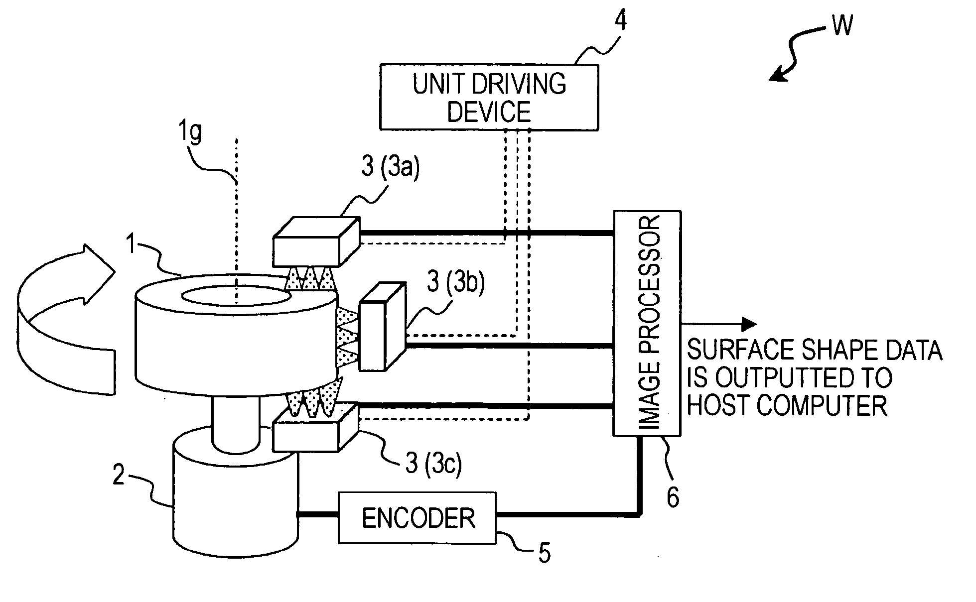
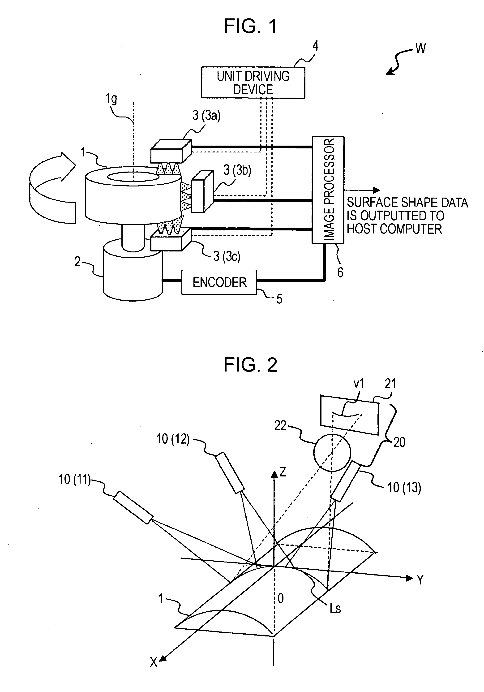
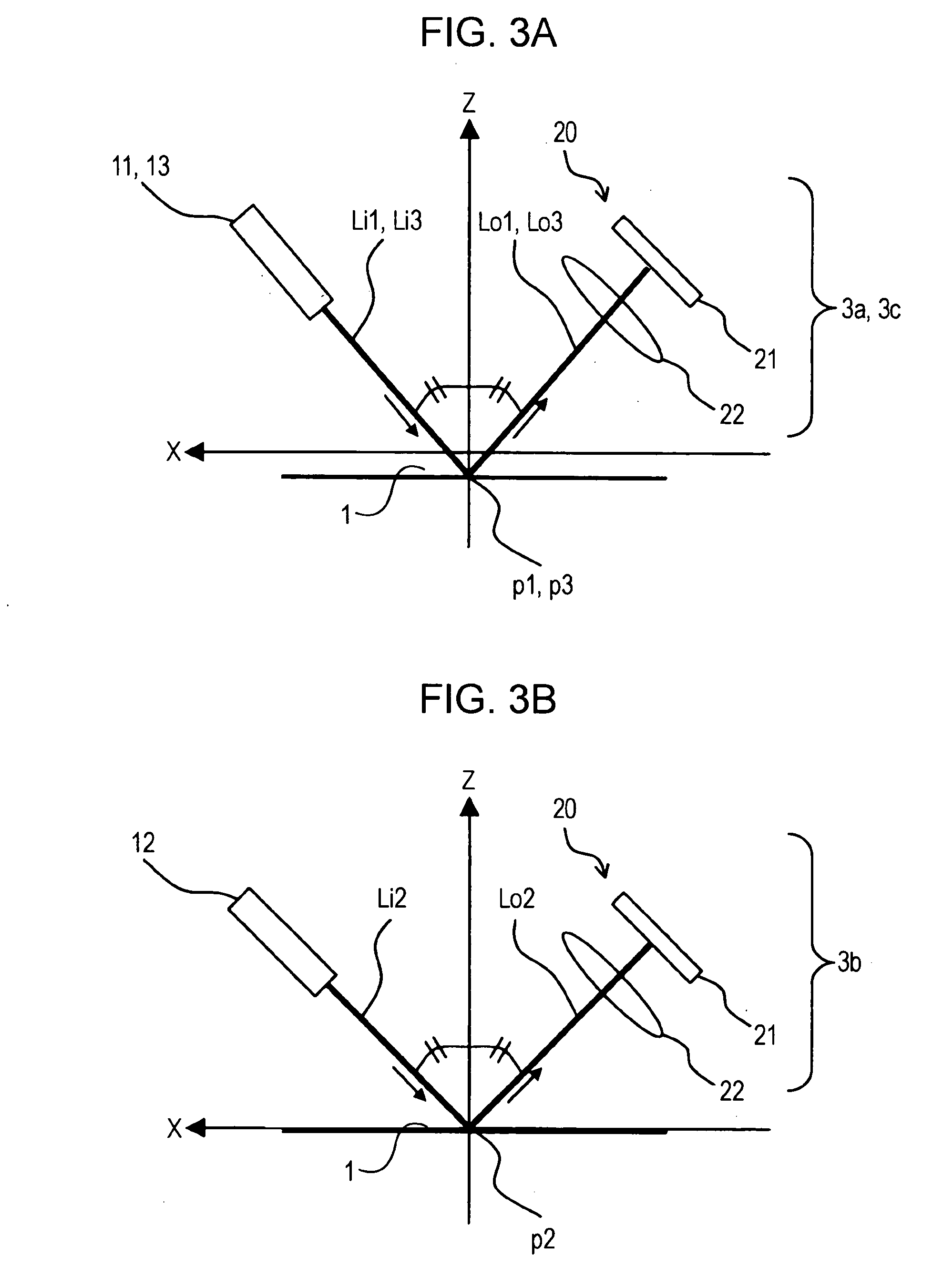
[0043]Here, FIG. 1 is a schematic diagram showing the construction of a tire shape detecting apparatus W according to an embodiment of the present invention; FIG. 2 is a schematic diagram showing three-dimensional installation of light sources and a camera in a sensor unit included in the tire shape detecting apparatus W; FIGS. 3A and 3B are schematic diagrams each showing the installation of the source(s) of light and the camera in sensor unit(s), when viewed from a specific direction (Y-axis direction); FIGS. 4A, 4B, and 4C are schematic diagrams each showing the installation of the source of light and the camera in the ...


PUM


Abstract

A tire shape detecting apparatus includes a projector that applies a plurality line light beams in a continuously joined manner, from a direction different from the detection height direction (Z-axis direction) in one light section line, or that applies one line light beam in a condensed manner in the line length direction thereof in order that the one light section line may be formed on the one line Ls on the surface of the tire; and a camera for picking up images of the plurality of line light beams applied to the tire surface in the direction in which the principal ray of each of the plurality of line light beams performs specular reflection with respect to the tire surface, or in the direction in which the principal ray of the condensed one line light beam performs specular reflection with respect to the tire surface.

Description

BACKGROUND OF THE INVENTION[0001]1. Field of the Invention[0002]The present invention related to an apparatus and method for picking up an image of line light applied to the surface of a relatively rotating tire, and for performing shape detection of the tire by the light-section method based on the picked-up image, to thereby detect the surface shape of the tire.[0003]2. Description of the Related Art[0004]The tire has a structure such that various materials such as rubber, chemical fibers, and steel cords are laminated. If there are nonuniform portions in the laminated structure, when air is charged, convex portions referred to as bulges, or concave portions referred to as dents or depressions occur in portions having a relatively low resistance to pressure. Tires causing shape defects such as the aforementioned bulges or dents must be omitted from a shipping object upon being subjected to inspection, from the viewpoint of safety or the viewpoint of the elimination of nonconformin...

Claims


Application Information

Patent Timeline
IPC IPC(8): G01N21/00G01N21/55B60C19/00G01B11/24
CPCG01M17/027
Inventor SAKODA, NAOKAZUTAKAHASHI, EIJIMORIMOTO, TSUTOMUMATSUSHITA, YASUHIRONONAKA, TOSHIKATSUHORIGUCHI, SHIRO
Owner KOBE STEEL LTD
Learn More