Light scanning apparatus, light scanning method, image forming apparatus, and color image forming apparatus

a technology of light scanning and light scanning, which is applied in the direction of electrical devices,pictoral communication, etc., can solve the problems of fluctuation of the amount of light emitted from the light source, the difficulty of maintaining the light intensity of the semiconductor laser at a specific level, and the difficulty of improving printing speed and image quality with such conventional methods

Inactive Publication Date: 2008-09-11
RICOH KK
View PDF0 Cites 34 Cited by
  • Summary
  • Abstract
  • Description
  • Claims
  • Application Information

AI Technical Summary

Benefits of technology

[0044]According to this aspect of the present invention, it is possible to provide a high-accuracy image forming apparatus capable of forming fine (clear) images.
[0045]According to an aspect of the present invention, there is provided a color image formin

Problems solved by technology

However, further improvements in printing speed and image quality would be difficult with such conventional methods.
However, since the light output of a semiconductor laser at a driving current varies depending on the temperature, it is difficult to maintain the light intensity of a semiconductor laser at a specific level.
Especially, in a surface emitting laser array having plural light sources on a single chip, since the distances between the light sources are short, temperature variation due to light emission and extinction and temperature cross-talk is likely to cause fluctuation of the amount of light emitted from the light sourc

Method used


Image

  • Light scanning apparatus, light scanning method, image forming apparatus, and color image forming apparatus
  • Light scanning apparatus, light scanning method, image forming apparatus, and color image forming apparatus
  • Light scanning apparatus, light scanning method, image forming apparatus, and color image forming apparatus

Examples


Embodiment Construction

[0098]Preferred embodiments of the present invention are described hereinafter with reference to the accompanying drawings. It is to be noted that, in the present invention, a pixel indicates a simple pixel (e.g. a pixel in a 1,200 dpi image has a size of about 21 μm square), and does not indicate a compound pixel formed of plural pixels (e.g. 4×4 pixels) as in a dither matrix.

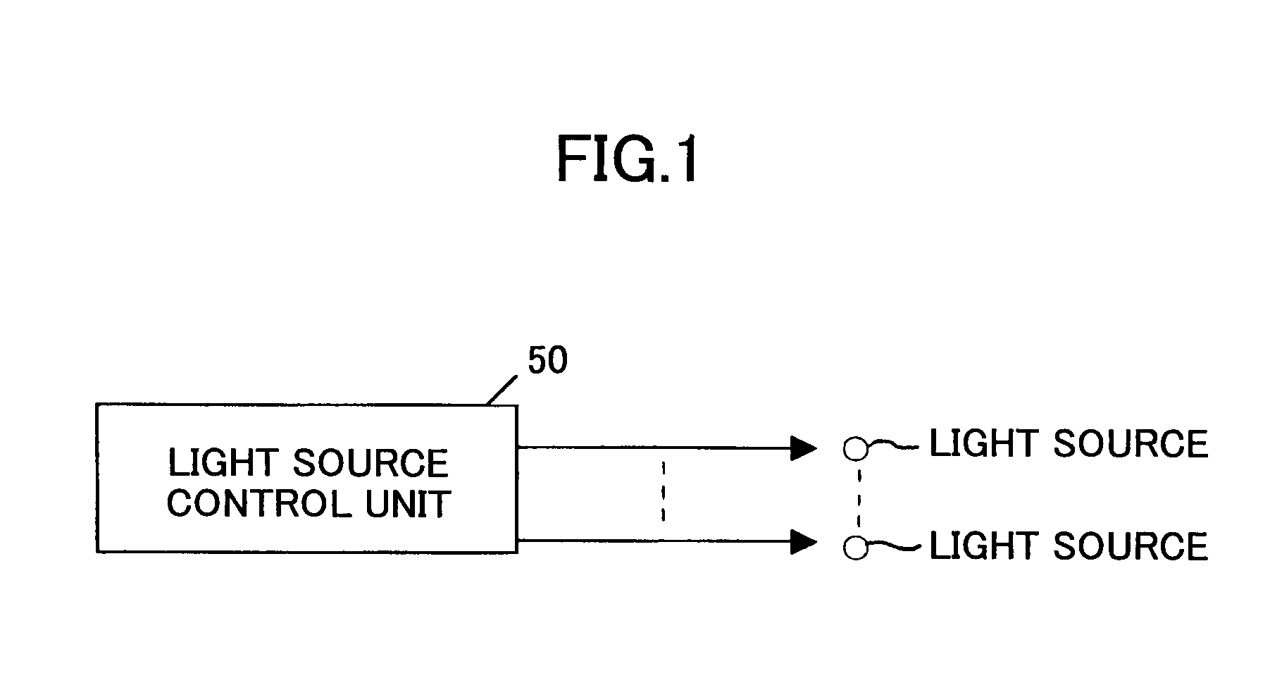
[0099]FIG. 1 is a diagram showing an exemplary configuration of a light scanning apparatus according to an embodiment of the present invention. As shown in FIG. 1, a light scanning apparatus according to an embodiment of the present invention (a light scanning apparatus that scans plural light beams from plural light sources in the main scanning direction) includes a light source control unit 50 that controls plural light sources. When plural light sources (e.g. a two-dimensional array of plural light sources) are used, the arrangement of light emitting points of the light sources may not always correspond to ...


PUM


Abstract

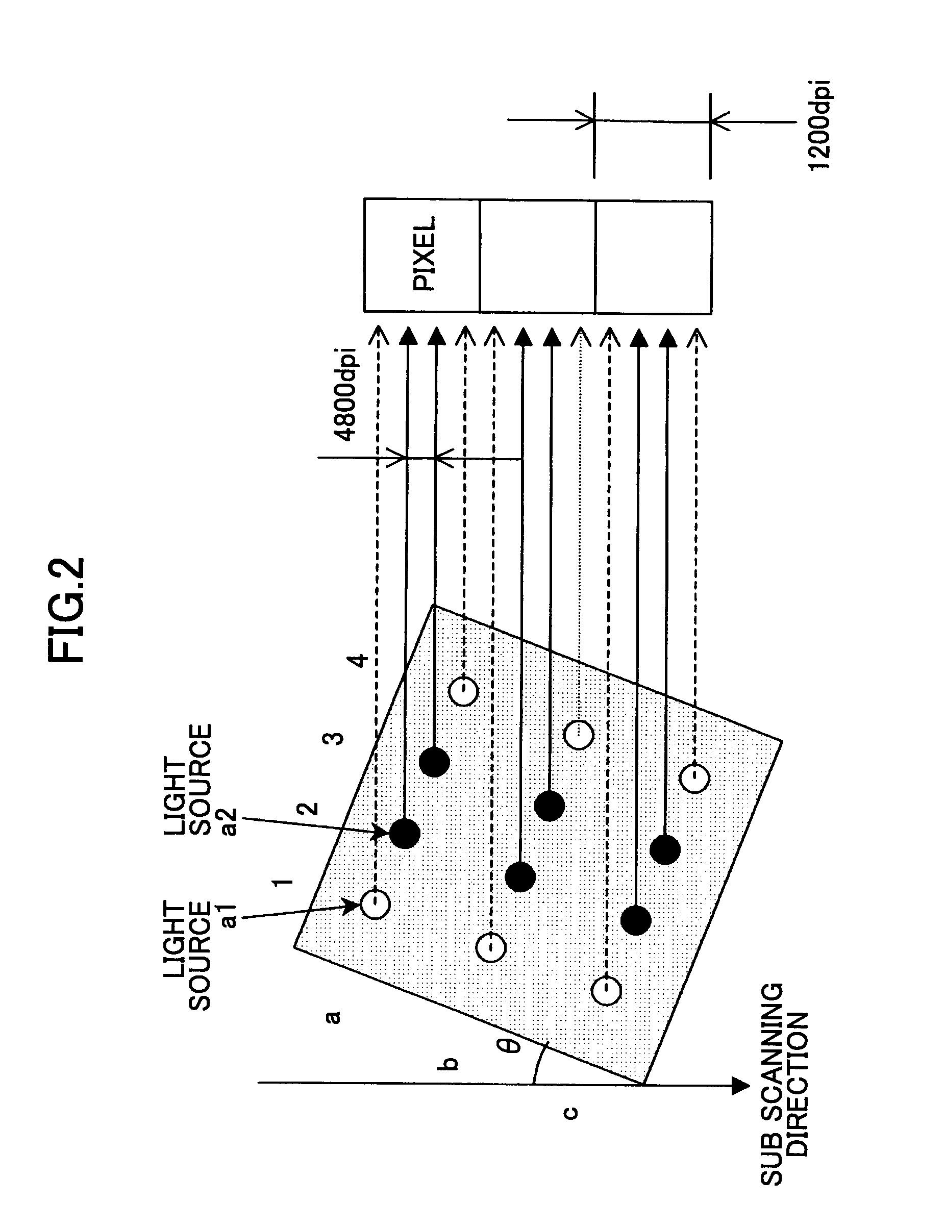
A light scanning apparatus is provided that has plural light sources which scan plural light beams in a main scanning direction. The light scanning apparatus comprises a light source control unit that controls the plural light sources. Where an array of N (N≧2) light sources aligned in a sub scanning direction and capable of scanning different positions in the sub scanning direction is called a virtual light source array, and where L (L≧2) virtual light source arrays aligned in the sub scanning direction are formed, the light source control unit causes M ((N−1)≧M≧1) light sources out of the N light sources of each of the L virtual light source arrays to emit light to form a pixel and thereby to form a total of L pixels aligned in the sub scanning direction by giving the same data to the M light sources of each of the L virtual light source arrays.

Description

BACKGROUND OF THE INVENTION[0001]1. Field of the Invention[0002]The present invention relates to a light scanning apparatus, a light scanning method, an image forming apparatus, and a color image forming apparatus.[0003]2. Description of the Related Art[0004]FIG. 23 is a block diagram illustrating an exemplary configuration of an electrophotographic image forming apparatus such as a laser printer or a digital copier. Referring to FIG. 23, a laser beam emitted from a semiconductor laser unit 1001 used as a light source unit is deflected and scanned by a rotating polygon mirror 1002, passes through a scanning lens (fθ lens) 1003, and forms a light spot on a photoreceptor 1004. The photoreceptor 1004 is exposed to light, so that an electrostatic latent image is formed. A phase-locked loop 1009 synchronizes the phase of a modulation signal generated by a clock generation circuit 1008 with the phase of an output signal from a photodetector 1005 that detects the laser beam deflected by th...

Claims


Application Information

Patent Timeline
IPC IPC(8): H04N1/04
CPCH04N1/0473H04N1/1912H04N2201/04787H04N2201/0082H04N1/1917
Inventor TANABE, JUNISHIDA, MASAAKINIHEI, YASUHIROOMORI, ATSUFUMI
Owner RICOH KK
Why Eureka
Try Eureka