Optical receiving apparatus and balance adjustment method

a technology of optical receiving apparatus and balance adjustment method, which is applied in the direction of electromagnetic transmission, transmission monitoring, electromagnetic transceivers, etc., can solve the problems of receiving demodulated signals that undergo deterioration in reception sensitivity, and it is extremely difficult to obtain a balanced receiver including first and second receiving elements, so as to improve the performance of the receiver

Inactive Publication Date: 2008-09-11
NEC CORP
View PDF3 Cites 8 Cited by
  • Summary
  • Abstract
  • Description
  • Claims
  • Application Information

AI Technical Summary

Benefits of technology

[0013]Accordingly, it is an object of the present invention to provide a balanced receiver in which deterioration in reception sensitivity, brought about by unbalanced characteristics in the balanced receiver, may be suppressed to improve the receiver's performance, and a balance adjustment method.
[0030]According to the present invention, it is possible to suppress deterioration in reception sensitivity, otherwise generated due to unbalance in amplitude, delay and frequency characteristics, by adjusting the balance in the balanced receiver, thereby improving the receiver's performance.

Problems solved by technology

It is extremely difficult to obtain a balanced receiver including first and second receiving elements whose amplitude, delay and frequency characteristics are the same.
The received demodulated signal undergoes deterioration in reception sensitivity due to unbalanced characteristics of the balanced receiver.

Method used


Image

  • Optical receiving apparatus and balance adjustment method
  • Optical receiving apparatus and balance adjustment method
  • Optical receiving apparatus and balance adjustment method

Examples


Embodiment Construction

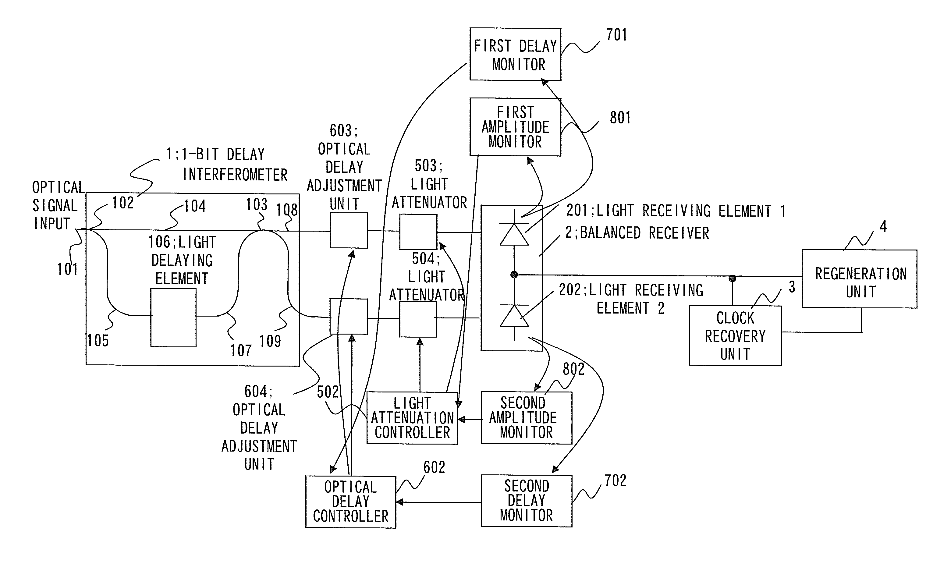
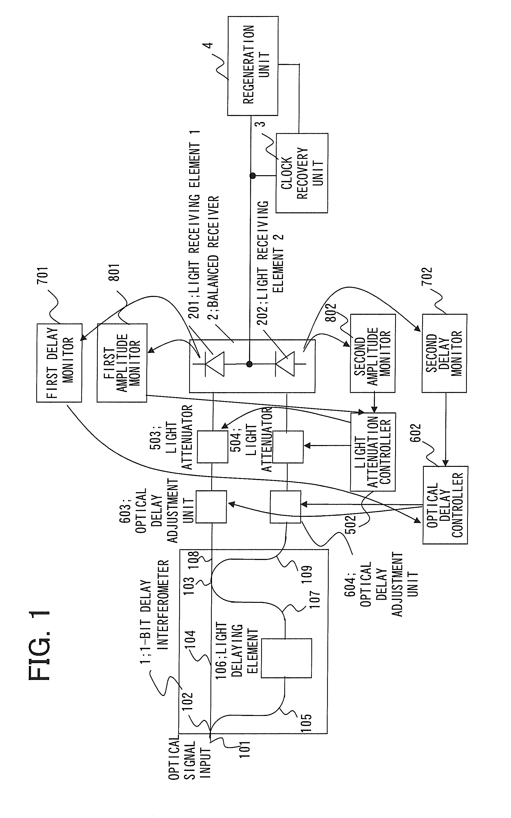
[0037]FIG. 1 shows the configuration of an optical receiving apparatus according to a first example of the present invention. Referring to FIG. 1, in the optical receiving apparatus according to the present example, there are provided, in addition to the customary configuration shown in FIG. 5, a light attenuation controller 502, light attenuators 503 and 504, an optical delay controller 602, optical delay adjustment units 603 and 604, first and second delay monitors 701 and 702 and first and second amplitude monitors 801 and 802. In FIG. 1, a 1-bit delay interferometer 1, a balanced receiver 2, a clock recovery unit 3 and a regeneration unit 4 are the same as the corresponding components shown in FIG. 5 and hence are not here reiteratively described for simplicity.

[0038]In the present example, signals from two ports of output waveguides 108 and 109 of the 1-bit delay interferometer 1 (light intensity signals) are adjusted for delay by the optical delay adjustment units 603 and 604,...


PUM


Abstract

Disclosed is a optical receiving apparatus including a balanced receiver comprising first and second light receiving elements which receive respective optical signals from first and second ports of a 1-bit delay interferometer, monitor units that monitor amplitudes and delays at the first and second light receiving elements, respectively, control units that variably respectively control attenuations and delays on the paths between the first and second output ports of the 1-bit delay interferometer and the first and second light receiving elements, based on monitored results by the monitor units.

Description

REFERENCE TO RELATED APPLICATION[0001]This application is based upon and claims the benefit of the priority of Japanese patent application No. 2007-057346, filed on Mar. 7, 2007, the disclosure of which is incorporated herein in its entirety by reference thereto.FIELD OF THE INVENTION[0002]This invention relates to an optical receiving apparatus and, more particularly, to an optical receiving apparatus that includes a balanced receiver, and to a balance adjustment method.BACKGROUND OF THE INVENTION[0003]A DPSK (Differential Phase Shift Keying) modulation system, used for optical transmission, differentially encodes a phase change between information data sequences, generated from binary signals, to perform phase modulation on DC light. For example, a differentially encoded signal is generated in which the non-presence and the presence of a phase change between neighboring data symbols assume an ON-state and an OFF-state, respectively. To demodulate an optical signal which has been m...

Claims


Application Information

Patent Timeline
Patent Type & Authority Applications(United States)
IPC IPC(8): H04B10/06H01L31/10H04B10/40H04B10/07H04B10/50H04B10/516H04B10/548H04B10/564H04B10/60H04B10/61H04B10/67H04B10/69
CPCH04B10/677
Inventor OMORI, KUMIKOGA, TADASHI
Owner NEC CORP
Why Eureka
Try Eureka