
Extracorporeal Circulator

a circulator and extracorporeal technology, applied in the field of extracorporeal circulators, can solve the problem of insufficient removal of bubbles (completely) and achieve the effect of reducing priming volum

Active Publication Date: 2008-09-11
TERUMO KK
View PDF5 Cites 10 Cited by
  • Summary
  • Abstract
  • Description
  • Claims
  • Application Information

AI Technical Summary

Benefits of technology

The invention is an extracorporeal circulator that prevents bubbles from being fed to a patient. It includes a bubble removing unit that removes bubbles from the blood using a circulation flow forming chamber and a vacuum chamber. The bubble removing unit also has a bubble detection system to reliably prevent bubbles from accumulating in the circulator. The blood-feed control means controls the operation of the blood pump to prevent bubbles from being fed to the patient. The invention reduces the amount of blood needed for the extracorporeal circulation, while also reducing the priming volume. It is designed to provide smooth and appropriate extracorporeal circulation.

Problems solved by technology

However, with the bubble removing unit, when excessive bubbles (gas) accumulate in the blood inflow space (bubble reservoir), the bubbles sometimes pass through the filter, posing the possibility that the bubbles are not sufficiently (completely) removed, so that they may flow out of the bubble removing unit together with the filtered blood.

Method used


Image

  • Extracorporeal Circulator
  • Extracorporeal Circulator
  • Extracorporeal Circulator

Examples


first embodiment

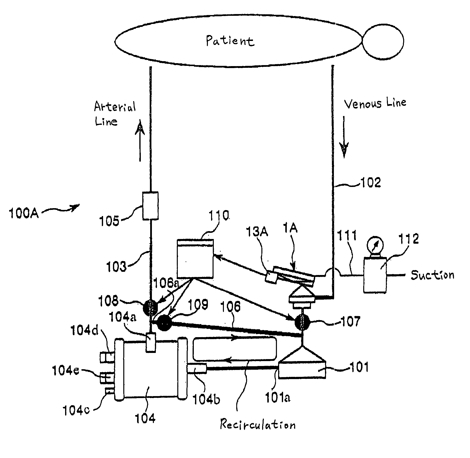
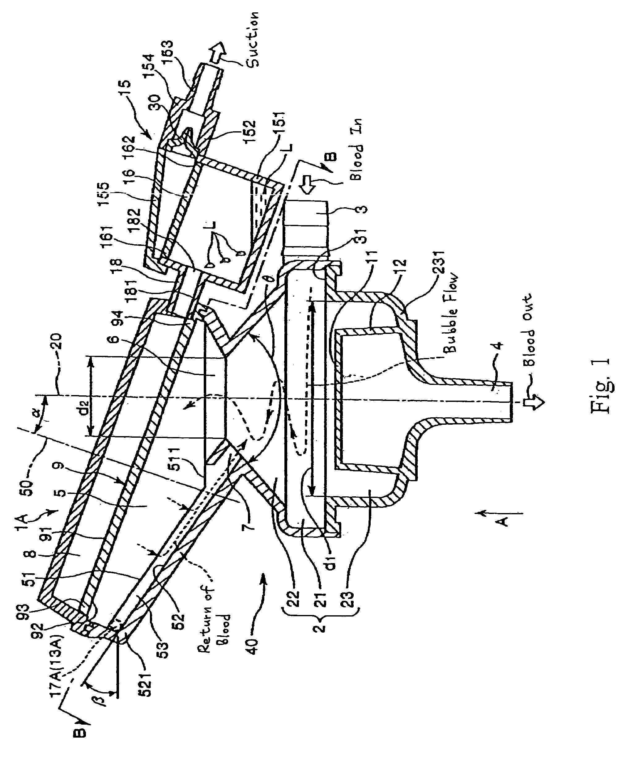
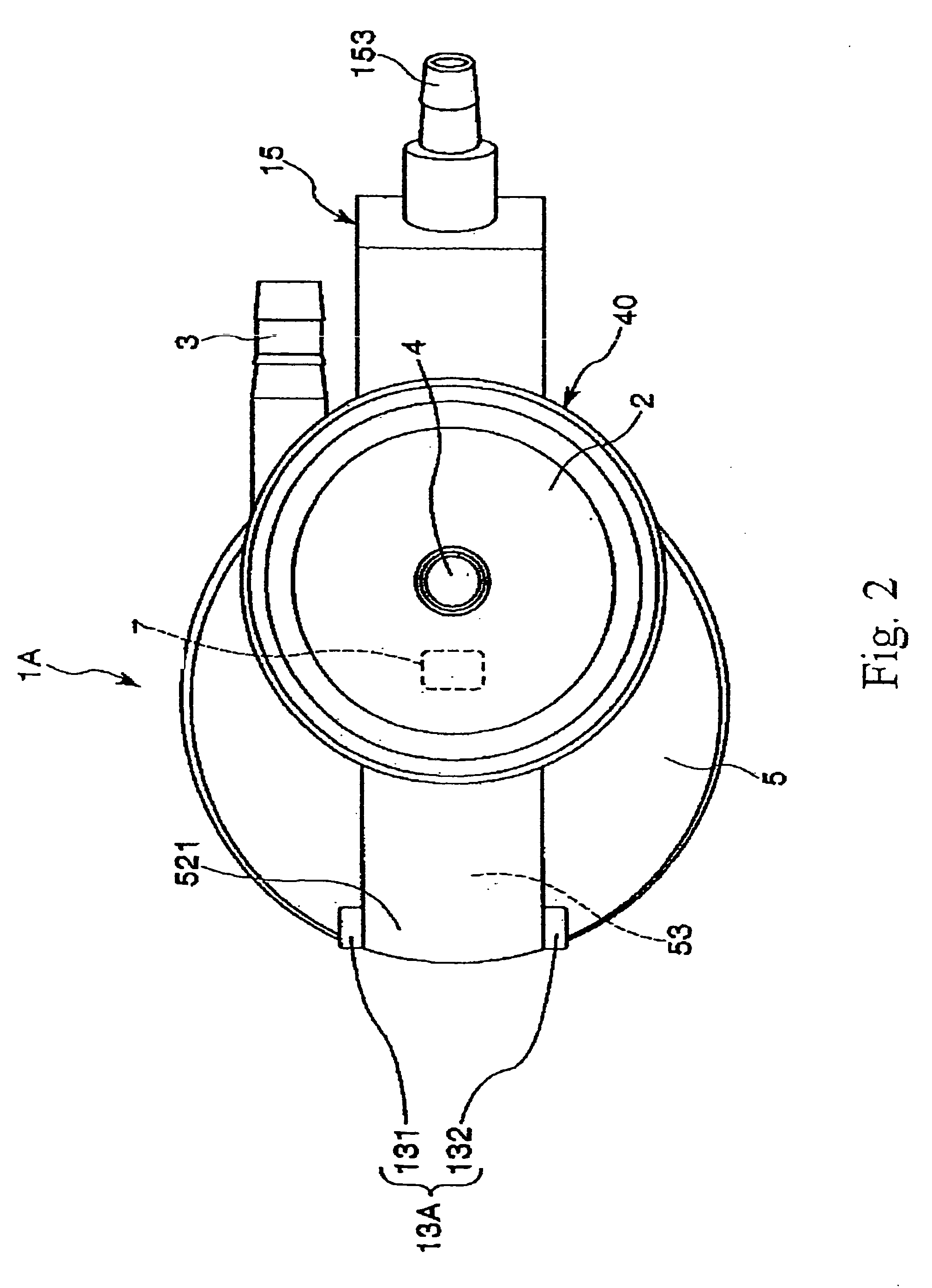
[0061]FIG. 1 is a cross-sectional side view of a bubble removing unit of an extracorporeal circulator (a first embodiment) of the invention; FIG. 2 is an arrow diagram (bottom view) of the unit taken on arrow A of FIG. 1; FIG. 3 is a sectional view of the unit taken along line B-B of FIG. 1; and FIG. 4 is a schematic diagram of the extracorporeal circulator of the first embodiment of the invention. The upper part in FIG. 1 is referred to as “the upper part” or “above”, and the lower part is referred to as “the lower part” or “below” for the convenience of description.

[0062]A bubble removing unit 1A of an extracorporeal circulator 100A will first be described.

[0063]The bubble removing unit 1A in the drawings is for removing the bubbles (gas) in the blood circulating extracorporeally. The bubble removing unit 1A can be used in both an extracorporeal circulation in which no blood is circulated in patient's heart, no gas exchange is performed in the patient's body, and blood circulation...

second embodiment

[0152]FIG. 5 is a cross-sectional side view of a bubble removing unit of an extracorporeal circulator (a second embodiment) of the invention; FIG. 6 is a schematic diagram of the extracorporeal circulator according to the second embodiment of the invention; FIG. 7 is a flowchart of the control program of a controller of the extracorporeal circulator of FIG. 6; and FIG. 8 is a graph showing changes in the rotation speed of the blood pump with time under the control of the controller of the extracorporeal circulator of FIG. 6. The upper part in FIG. 5 is referred to as “the upper part” or “above”, and the lower part is referred to as “the lower part” or “below” for the convenience of description.

[0153]The extracorporeal circulator of the embodiment of the invention will be described with reference to the drawings, in which the embodiment will be described hereinbelow with particular emphasis on differences from the above-described embodiment, and descriptions of like or corresponding ...


PUM


Abstract

An extracorporeal circulator comprising a line for extracting blood from a patient, a pump for supplying blood, an artificial lung section performing gas exchange on blood, a line for supplying blood passed through the artificial lung section to the patient, a unit for removing bubbles mixed into the blood, a controller for controlling the flow rate of blood being supplied such that bubbles are not fed to the patient, and a line for detouring blood delivered from the blood pump to return it to the blood pump.

Description

TECHNICAL FIELD [0001]The present invention relates to an extracorporeal circulator comprising a blood pump for transferring blood to circulate it extracorporeally, a bubble removing unit for removing bubbles in the extracorporeally circulating blood, and means for controlling the operation of the blood pump.BACKGROUND ART [0002]For example, during cardiac surgeries, artificial-lung extracorporeal circulation is generally performed in which patient's blood is drawn from the vein (the vena cava) of the patient by a blood pump, and the gas is exchanged by an artificial lung, and then the blood is returned to the artery of the patient.[0003]A circuit for such extracorporeal circulation (an extracorporeal circulation circuit) is equipped with a bubble removing unit for removing (separating) bubbles flowing in the drawn blood. Known bubble removing units include a unit including a housing (container body) and a filter disposed in the housing and partitioning the housing into a blood infl...

Claims


Application Information

Patent Timeline
Patent Type & Authority Applications(United States)
IPC IPC(8): A61M1/36
CPCA61M1/3627A61M1/32A61M1/3603
Inventor OGIHARA, MITSUAKINAKAYAMA, HIDETAKATAKEUCHI, KAZUHIKOISHIKURA, YUKIITO, AKIYASU
Owner TERUMO KK
Learn More