METHOD FOR PRODUCING A TOOL WHICH CAN BE USED TO CREATE OPTICALLY ACTIVE SURFACE STRUCTRES IN THE SUB-nuM RANGE AND A CORRESPONDING TOOL

a technology of optical active surface and tool, which is applied in the direction of glass shaping apparatus, ion implantation coating, coating, etc., can solve the problems of disturbing and energy-diminishing effects of light reflection on technical and optical surfaces and interfaces, significantly reducing the efficiency of solar cells, and affecting the readability of displays

Inactive Publication Date: 2008-09-18
FRAUNHOFER GESELLSCHAFT ZUR FOERDERUNG DER ANGEWANDTEN FORSCHUNG EV
View PDF6 Cites 2 Cited by
  • Summary
  • Abstract
  • Description
  • Claims
  • Application Information

AI Technical Summary

Benefits of technology

[0011]The present invention is a method for producing a tool and to provide the tool which can be utilized for fabricating optically active surface structures in the sub-μm range and which has a support surface on which relief surface structures are applied over the support structure by means of material deposition that, on the one hand, prevents the drawbacks arising with the aforedescribed stochastic surface structures, that is undesirable high diffuse and direct reflection, and, on the other hand, nonetheless ensures utilizing the tool under high temperatures in order to be able to provide antireflective optical or technical surfaces made of not only organic materials but also of inorganic materials with it.
[0014]By dividing the coating procedure into two parts, single surface structure elements are obtained whose lateral structure dimensions diminish with increasing height of the structure due to the subsequent, preferred material deposition on the coating seeds. In this manner, column-like formations with diminishing diameters are formed as surface structures on the support surface. In this manner protrusions can be completely avoided so that transfer of the surface structure onto optical or technical surfaces is readily possible in a molding procedure.
[0019]With the aid of such a coating, it is possible to produce a high-temperature resistant layer which can withstand even temperatures up to over 850° C. and permits molding of the surface structure on optical or technical surfaces made not only of organic, preferably, light-transparent plastics but, in particular, also structures composed of inorganic materials, such as glass.

Problems solved by technology

In many light-optical applications, reflections of light have a disturbing and energy-diminishing effect on technical and optical surfaces and interfaces.
For example, the readability of displays is distinctly impaired by the reflection of external light sources.
Furthermore, in the case of glazed solar cell modules, reflection losses occur on the cover thereby considerably reducing the solar cell's efficiency.
These surface finishes are, however, not only expensive but also unsatisfactory, because their effect depends largely on the angle of incidence and the wavelength of the light impinging on the surfaces.
They, however, have the drawback that they are produced with nickel.
However, such types of stamps, also called “masters”, possess low high-temperature resistance due to the material they are made of, and can therefore only be utilized for shaping the surface of organic glasses, such as for example optical elements made of PMMA.
Moreover, the lifetime of such nickel master tools is short as distinct wear can be observed with repeated use due to their material.
Finally, the production method of periodic structures using photolithography has the disadvantage that open surfaces or aspherical surfaces, often needed in technology, cannot be structured.
The presence of large structural elements within the microstructure surface, however, leads to an undesiderable increase in diffuse reflection and at the same time to a decrease in direct reflection when being formed.
The selective, diamond coated substrate yielded by this method meets microelectronic needs, but it cannot be used as a heat-resistant tool, in the sense described in the introduction, due to the purposely selective coating.

Method used


Image

  • METHOD FOR PRODUCING A TOOL WHICH CAN BE USED TO CREATE OPTICALLY ACTIVE SURFACE STRUCTRES IN THE SUB-nuM RANGE AND A CORRESPONDING TOOL
  • METHOD FOR PRODUCING A TOOL WHICH CAN BE USED TO CREATE OPTICALLY ACTIVE SURFACE STRUCTRES IN THE SUB-nuM RANGE AND A CORRESPONDING TOOL
  • METHOD FOR PRODUCING A TOOL WHICH CAN BE USED TO CREATE OPTICALLY ACTIVE SURFACE STRUCTRES IN THE SUB-nuM RANGE AND A CORRESPONDING TOOL

Examples


Embodiment Construction

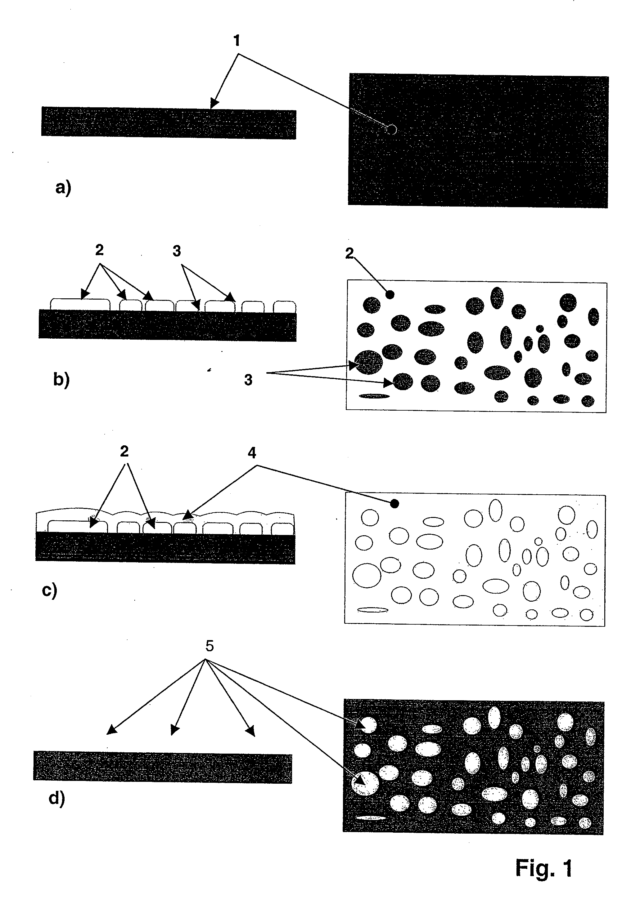
[0025]FIGS. 1a) to d) show on the left a lateral view and on the right a top view of the respective steps of the method. FIG. 1a depicts a lateral and a top view of the support of a tool, with a support surface 1 which is to be selectively coated. In FIG. 1b), a mask 2, which is provided with a multiplicity of openings 3 where the support surface 1 is surrounded free of the material of mask 2, is placed directly on the support surface 1. The mask material 2 can, for example, comprise a photoresist, which is removed locally and selectively at the sites of openings 3 after corresponding exposure and the subsequent etching process. Depending on the manner of exposure, the openings 3 form in a specific configuration within the mask 2. A top view of FIG. 1b) shows an example of opening geometry and a corresponding configuration. The openings 3 represent dark areas on the support surface with the remaining white areas being covered by the mask material 2.

[0026]The mask 2 provided with ope...


PUM

PropertyMeasurementUnit
heightsaaaaaaaaaa
heightsaaaaaaaaaa
heightsaaaaaaaaaa

Abstract

The invention is a method for producing a tool which can be used to create optically active surface structures in the sub-μm range, having a support surface onto which relief surface structures are applied over the support surface by means of material deposition. The invention is distinguished by the support surface being directly contacted with a mask in which openings with diameters in the sub-μm range are provided or can be provided, by the support surface including the mask being subjected to a coating process in which the coating material deposits through the openings of the mask onto the support surface, and the mask is removed from the support surface when a partial amount of an average end structure height of the surface structures is reached and the coating procedure is then continued without the mask using the same coating material or different coating materials.

Description

BACKGROUND OF THE INVENTION[0001]1. Field of the Invention[0002]The present invention relates to a method for producing a tool which can be used to create optically active surface structures in the sub-μm range, having a support surface onto which relief surface structures are applied by means of the deposition of materials. Furthermore, a corresponding tool is described.[0003]2. Description of the Prior Art[0004]In many light-optical applications, reflections of light have a disturbing and energy-diminishing effect on technical and optical surfaces and interfaces. For example, the readability of displays is distinctly impaired by the reflection of external light sources. Furthermore, in the case of glazed solar cell modules, reflection losses occur on the cover thereby considerably reducing the solar cell's efficiency.[0005]To decrease reflection and increase transmission, technically complicated single layer or multi-layer systems have hitherto been applied to the surfaces in orde...

Claims


Application Information

Patent Timeline
Patent Type & Authority Applications(United States)
IPC IPC(8): B05C11/00C03B11/08C03C17/25C03C19/00C23C14/04
CPCC03B11/082C03B2215/412C23C14/042C03C2217/77C03C17/25
Inventor BURMEISTER, FRANKDOLL, WALTERKLEER, GUNTER
Owner FRAUNHOFER GESELLSCHAFT ZUR FOERDERUNG DER ANGEWANDTEN FORSCHUNG EV
Why Eureka
Try Eureka